Evolution of Residential Real Estate in Toronto – 2014 to 2022

Shashank Prabhu, Geovis Project Assignment, TMU Geography, SA8905, Fall 2024 

Introduction
Toronto’s residential real estate market has experienced one of the most rapid price increases among major global cities. This surge has led to a significant affordability crisis, impacting the quality of life for residents. My goal with this project was to explore the key factors behind this rapid increase, while also analyzing the monetary and fiscal policies implemented to address housing affordability.

The Approach: Mapping Median House Prices
To ensure a more accurate depiction of the market, I used the median house price rather than the average. The median better accounts for outliers and provides a clearer view of housing trends. This analysis focused on all home types (detached, semi-detached, townhouses, and condos) between 2014 and 2022.

Although data for all years were analyzed, only pivotal years (2014, 2017, 2020, and 2022) were mapped to emphasize the factors driving significant changes during the period.

Data Source
The Toronto Regional Real Estate Board (TRREB) was the primary data source, offering comprehensive market watch reports. These reports provided median price data for Central Toronto, East Toronto, and West Toronto—TRREB’s three primary regions. These regions are distinct from the municipal wards used by the city.

Creating the Maps

Step 1: Data Preparation
The Year-to-Date (YTD) December figures were used to capture an accurate snapshot of annual performance. The median price data for each of the years across the different regions was organized in an Excel sheet, joined with TRREB’s boundary file (obtained through consultation with the Library’s GIS department), and imported into ArcGIS Pro. WGS 1984 Web Mercator projection was used for the maps.

Step 2: Visualization with 3D Extrusions
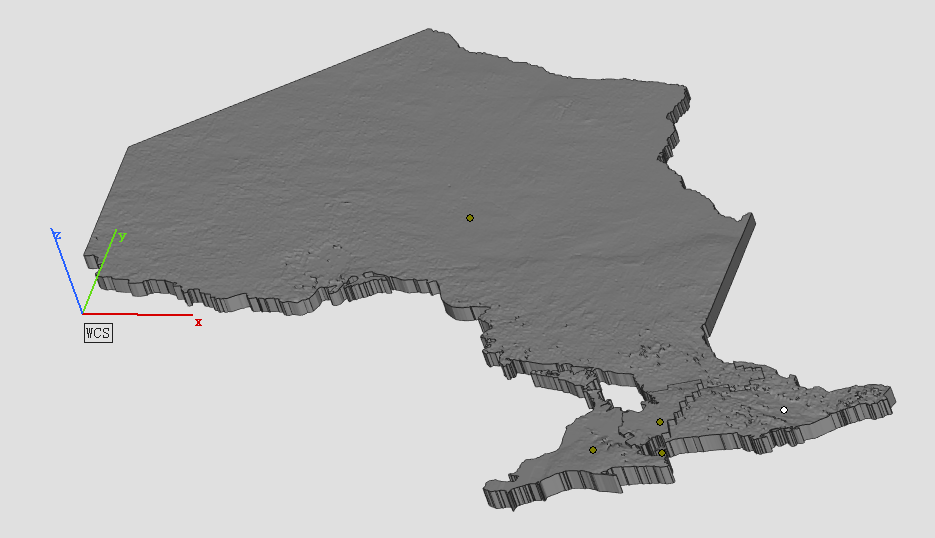
3D extrusions were used to represent price increases, with the height of each bar corresponding to the median price. A green gradient was selected for visual clarity, symbolizing growth and price.

Step 3: Overcoming Challenges

After creating the 3D extrusion maps for the respective years (2014, 2017, 2020, 2022), the next step was to export those maps to ArcOnline and then to Story Maps, the easiest way of doing so was to export it as a Web Scene, from which it would show up under the Content section on ArcOnline.

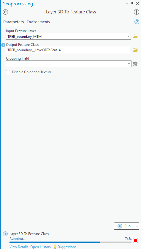
  • Flattened 3D Shapes: Exporting directly as a Web Scene to add onto Story Maps caused extrusions to lose their 3D properties. This was resolved using the “Layer 3D to Feature Class” tool.

  • Lost Legends: However, after using the aforementioned tool, the Legends were erased during export. To address this, static images of the legends were added below each map in Story Maps.

Step 4: Finalizing the Story Map
After resolving these issues, the maps were successfully exported using the Export Web Scene option. They were then embedded into Story Maps alongside text to provide context and analysis for each year.

Key Insights
The project explored housing market dynamics primarily through an economic lens.

  • Interest Rates: The Bank of Canada’s overnight lending rate played a pivotal role, with historic lows (0.25%) during the COVID-19 pandemic fueling a housing boom, and sharp increases (up to 5% by 2023) leading to market cooling.
  • Immigration: Record-breaking immigration inflows also contributed to increased demand, exacerbating the affordability crisis.

While earlier periods like 2008 were critical in shaping the market, boundary changes in TRREB’s data made them difficult to include.

Conclusion
Analyzing real estate trends over nearly a decade and visualizing them through 3D extrusions offers a profound insight into the rapid rise of residential real estate prices in Toronto. This approach underscores the magnitude of the housing surge and highlights how policy measures, while impactful, have not fully addressed the affordability crisis.

The persistent rise in prices, even amidst various interventions, emphasizes the critical need for increased housing supply. Initiatives aimed at boosting the number of housing units in the city remain essential to alleviate the pressures of affordability and meet the demands of a growing population.

Link to Story Map (You will need to sign in through your TMU account to view it): https://arcg.is/WCSXG

3D String Mapping and Textured Animation: An Exploration of Subway Networks in Toronto and Athens

BY: SARAH DELIMA

SA8905 – Geovis Project, MSA Fall 2024

INTRODUCTION:

Greetings everyone! For my geo-visualization project, I wanted to combine my creative skills of Do It Yourself (DIY) crafting with the technological applications utilized today. This project was an opportunity to be creative using resources I had from home as well as utilizing the awesome applications and features of Microsoft Excel, ArcGIS Online, ArcGIS Pro, and Clipchamp.

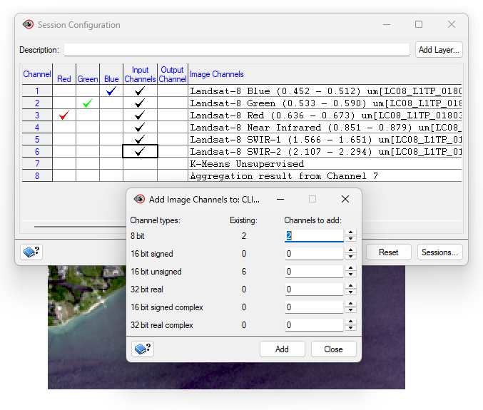
In this blog, I’ll be sharing my process for creating a 3D physical string map model. To mirror my physical model, I’ll be creating a textured animated series of maps. My models display the subway networks of two cities. The first being the City of Toronto, followed by the metropolitan area of Athens, Greece.

Follow along this tutorial to learn how I completed this project!

PROJECT BACKGROUND:

For some background, I am more familiar with Toronto’s subway network. Fortunately enough, I was able to visit Athens and explore the city by relying on their subway network. As of now, both of these cities have three subway lines, and are both undergoing construction of additional lines. My physical model displays the present subway networks to date for both cities, as the anticipated subway lines won’t be opening until 2030. Despite the hands-on creativity of the physical model, it cannot be modified or updated as easily as a virtual map. This is where I was inspired to add to my concept through a video animated map, as it visualizes the anticipated changes to both subway networks!

PHYSICAL MODEL:

Materials Used:

  • Paper (used for map tracing)
  • Pine wood slab
  • Hellman ½ inch nails
  • Small hammer
  • Assorted colour cotton string
  • Tweezers
  • Krazy glue

Methods and Process:

For the physical model, I wanted to rely on materials I had at home. I also required a blank piece of paper for a tracing the boundary and subway network for both cities. This was done by acquiring open data and inputting it into ArcGIS Pro. The precise data sets used are discussed further in my virtual model making. Once the tracings were created, I taped it to a wooden base. Fortunately, I had a perfect base which was pine wood. I opted for hellman 1/2 inch nails as the wood was not too thick and these nails wouldn’t split the wood. Using a hammer, each nail was carefully placed onto the the tracing outline of the cities and subway networks .

I did have to purchase thread so that I could display each subway line to their corresponding colour. The process of placing the thread around the nails did require some patience. I cut the thread into smaller pieces to avoid knots. I then used tweezers to hold the thread to wrap around the nails. When a new thread was added, I knotted it tightly around a nail and applied krazy glue to ensure it was tightly secured. This same method was applied when securing the end of a string.

Images of threading process:

City of Toronto Map Boundary with Tracing

After threading the city boundary and subway network, the paper tracing was removed. I could then begin filling in the space of the boundary. I opted to use black thread for the boundary and fill, to contrast both the base and colours of the subway lines. The City of Toronto thread map was completed prior to the Athens thread map. The same steps were followed. Each city is on opposite sides of the wood base for convenience and to minimize the use of an additional wood base.

Of course, every map needs a title , legend, north star, projection, and scale. Once both of the 3D string maps were complete, the required titles and text were printed and laminated and added to the wood base for both 3D string maps. I once again used the nails and hammer with the threads to create both legends. Below is an image of the final physical products of my maps!

FINAL PHYSICAL MODELS:

City of Toronto Subway Network Model:

Athens Metropolitan Area Metro Network Model:

VIRTUAL MODEL:

To create the virtual model, I used ArcGIS Pro software to create my two maps and apply picture fill symbology to create a thread like texture. I’ll begin by discussing the open data acquired for the City of Toronto, followed by the Census Metropolitan Area of Athens to achieve these models.

The City of Toronto:

Data Acquisition:

For Toronto, I relied on the City of Toronto open data portal to retrieve the Toronto Municipal Boundary as well as TTC Subway Network dataset. The most recent dataset still includes Line 3, but was kept for the purpose of the time series map. As for the anticipated Eglinton line and Ontario line, I could not find open data for these networks. However, Metrolinx created interactive maps displaying the Ontario Line and Eglinton Crosstown (Line 5) stations and names. To note, the Eglinton Crosstown is identified as a light rail transit line, but is considered as part of the TTC subway network. 

To compile the coordinates for each station for both subway routes, I utilized Microsoft Excel to create 2 sheets, one for the Eglinton line and one for the Ontario line. To determine the location of each subway station, I used google maps to drop a pin in the correct location by referencing the map visual published by Metrolinx. 

Ontario Line Excel Table :

Using ArcGIS Pro, I used the XY Table to Point tool to insert the coordinates from each separate excel sheet, to establish points on the map. After successfully completing this, I had to connect each point to create a continuous line. For this, I used the Point to Line tool also in ArcGIS Pro.

XY Table to Point tool and Points to Line tool used to add coordinates to map as points and connect points into a continuous line to represent the subway route:

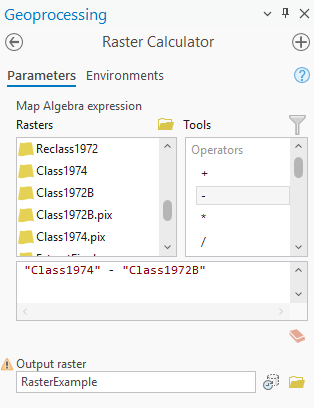
After achieving this, I did have to adjust the subway routes to be clipped within the boundary for The City of Toronto as well as Athens Metropolitan Area. I used the Pairwise Clip in the Geoprocessing pane to achieve this.

Geoprocessing pairwise clip tool parameters used. Note: The input features were the subway lines withe the city boundary as the clip features.

Athens Metropolitan Area:

Data Acquisition:

For retrieving data for Athens, I was able to access open data from Athens GeoNode I imported the following layers to ArcGIS Online; Athens Metropolitan Area, Athens Subway Network, and proposed Athens Line 4 Network which I added as accessible layers to ArcGIS online. I did have to make minor adjustments to the data, as the Athens metropolitan area data displays the neighbourhood boundaries as well. For the purpose of this project, only the outer boundaries were necessary. To overcome this, I used the merge modify feature to merge all the individual polygons within the metropolitan area boundary into one. I also had to use the pairwise clipping tool once again as the line 4 network exceeds the metropolitan boundary, thus being beyond the area of study for this project.

Adding Texture Symbology:

ArcGIS has a variety of tools and features that can enhance a map’s creativity and visualization. For this project , I was inspired by an Esri Yarn Map Tutorial. Given the physical model used thread, I wanted to create a textured map with thread. To achieve this, I utilized the public folder provided with the tutorial. This included portable network graphics (.png) cutouts of several fabrics as well as pen and pencil textures. To best mirror my physical model, I utilized a thread .png.

ESRI yarn map tutorial public folder:

I added the thread .png images by replacing the solid fill of the boundaries and subway networks with a picture fill. This symbology works best with a .png image for lines as it seamlessly blends with the base and surrounding features of the map. The thread .png image uploaded as a white colour, which I was able to modify its colour according to the boundary or particular subway line without distorting the texture it provides. 

For both the Toronto and Athens maps, the picture fill for each subway line and boundary was set to a thread .png with its corresponding colour. The boundaries for both maps were set to black as in the physical model, where the subway lines also mirror the physical model which is inspired by the existing/future colours used for subway routes. Below displays the picture symbology with the thread .png selected and tint applied for the subway lines.

City of Toronto subway Networks with picture fill of thread symbology applied:

The base map for the map was also altered, as the physical model is placed on a wood base. To mirror that, I extracted a Global Background layer from ArcGIS online, which I modified using the picture fill to upload a high resolution image of pine wood to be the base map for this model. For the city boundaries for both maps, the thread .png imagery was also applied with a black tint.

PUTTING IT ALL TOGETHER:

After creating both maps for Toronto and Athens, it was time to put it into an animation! The goal of the animation was to display each route, and their opening year(s) to visually display the evolution of the subway system, as my physical model merely captures the current subway networks. 

I did have to play around with the layers to individually capture each subway line. The current subway network data for both Toronto and Athens contain all 3 of their routes in one layer, in which I had to isolate each for the purpose of the time lapse in which each route had to be added in accordance to their initial opening date and year of most recent expansion. To achieve this, I set a Definition Query for each current subway route I was mapping whilst creating the animation.

Definition query tool accessed under layer properties:

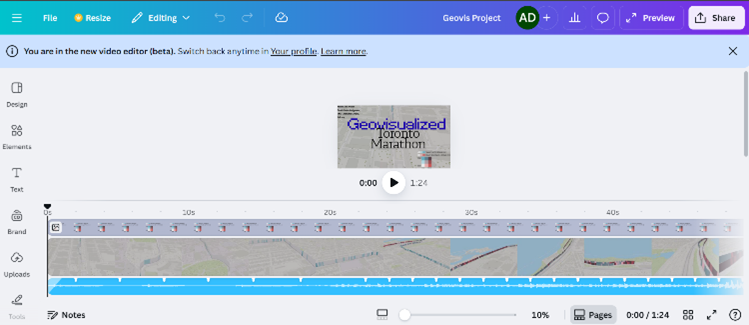
Once I added each keyframe in order of the evolution of each subway route, I created a map layout for each map to add in the required text and titles as I did with the physical model. The layouts were then exported into Microsoft Clipchamp to create the video animation. I imported each map layout in .png format. From there, I added transitions between my maps, as well as sound effects !

CITY OF TORONTO SUBWAY NETWORK TIMELNE:

Geovis Project, TMU Geography, SA8905 Sarah Delima

(@s1delima.bsky.social) 2024-11-19T15:05:37.007Z

ATHENS METROPOLITAN AREA METRO TIMELINE:

Geovis Project, TMU Geography, SA8905 Sarah Delima

(@s1delima.bsky.social) 2024-11-19T15:12:18.523Z

LIMITATIONS: 

While this project allowed me to be creative both with my physical and virtual models, it did present certain limitations. A notable limitation to this geovisualization for the physical model is that it is meant to be a mere visual representation of the subway networks.

As for the virtual map, although open data was accessible for some of the subway routes, I did have to manually enter XY coordinates for future subway networks. I did reference reputable maps of the anticipated future subway routes to ensure accuracy.  Furthermore, given my limited timeline, I was unable to map the proposed extensions of current subway routes. Rather, I focused on routes currently under construction with an anticipated completion date. 

CONCLUSION: 

Although I grew up applying my creativity through creating homemade crafts, technology and applications such as ArcGIS allow for creativity to be expressed on a virtual level. Overall, the concept behind this project is an ode to the evolution of mapping, from physical carvings to the virtual cartographic and geo-visualization applications utilized today.

Visualizing Population on a 3D-Printed Terrain of Ontario

Xingyu Zeng

Geovisual Project Assignment @RyersonGeo, SA8905, Fall 2022

Introduction

3D visualization is an essential and popular category in geovisualization. After a period of development, 3D printing technology has become readily available in people’s daily lives. As a result, 3D printable geovisualization project was relatively easy to implement at the individual level. Also, compared to electronic 3D models, the advantages of explaining physical 3D printed models are obvious when targeting non-professional users.

Data and Softwares

3D model in Materialise Magics
  • Data Source: Open Topography – Global Multi-Resolution Topography (GMRT) Data Synthesis
  • DEM Data to a 3D Surface: AccuTrans 3D – which provides translation of 3D geometry between the formats used by many 3D modeling programs.
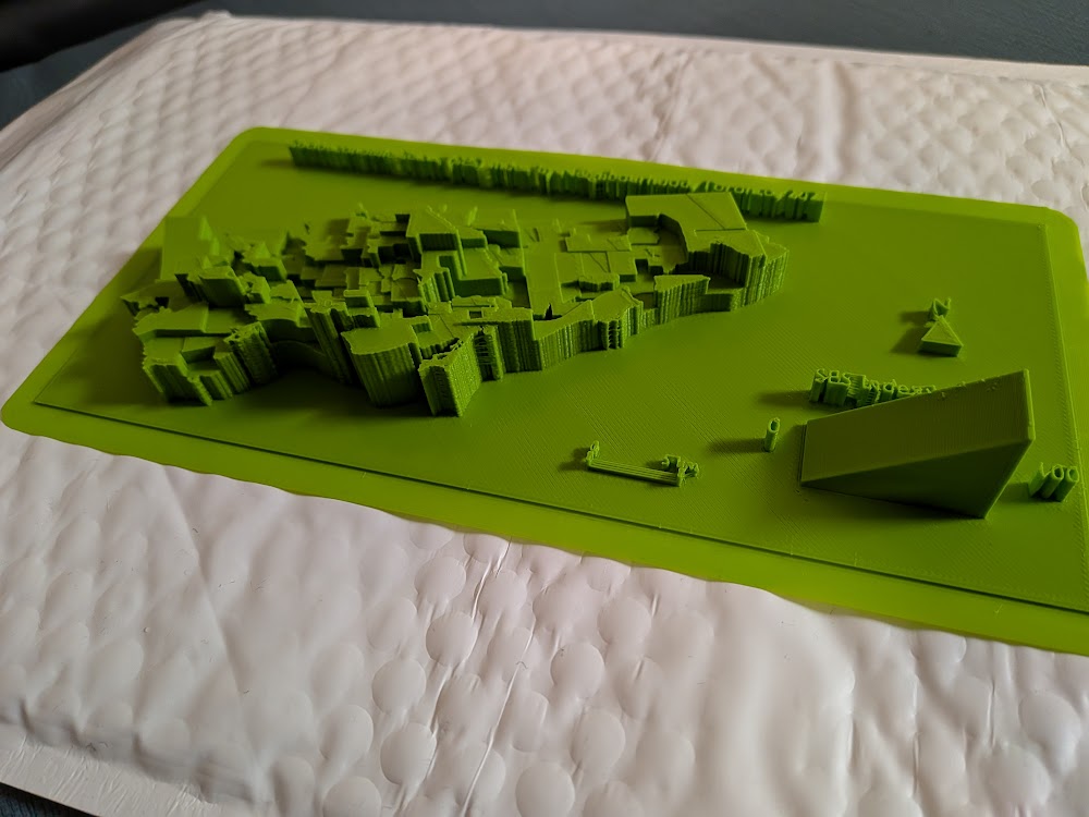
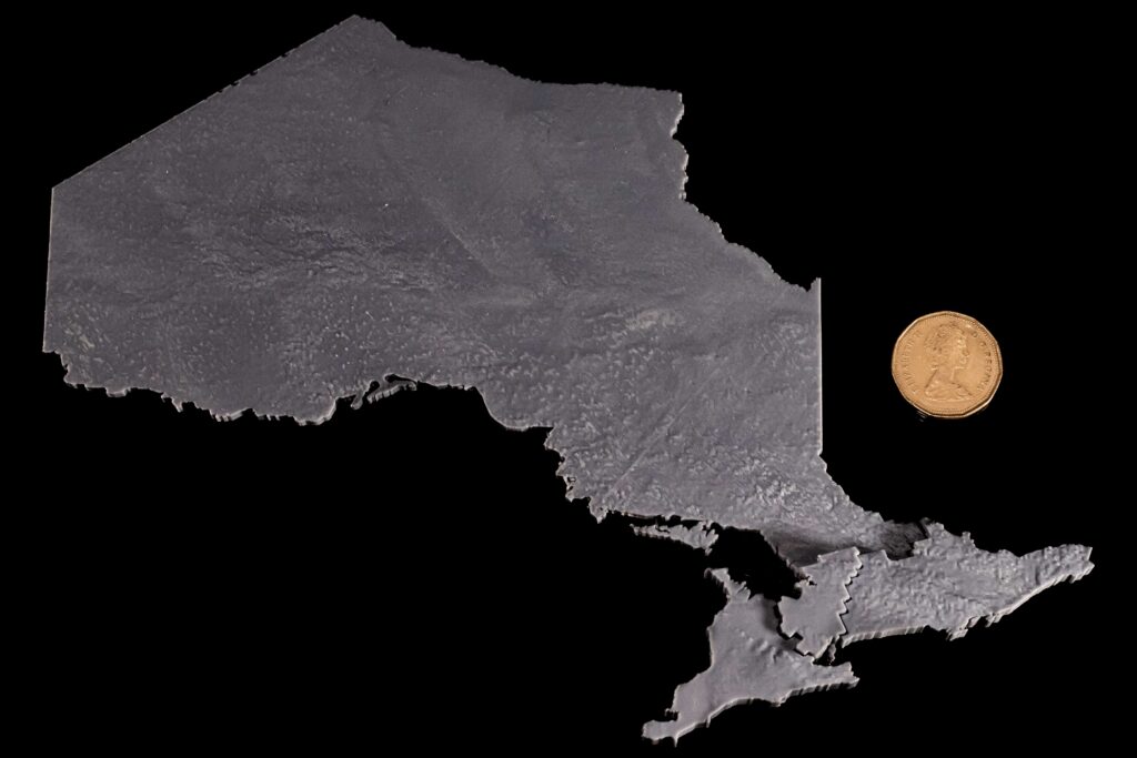
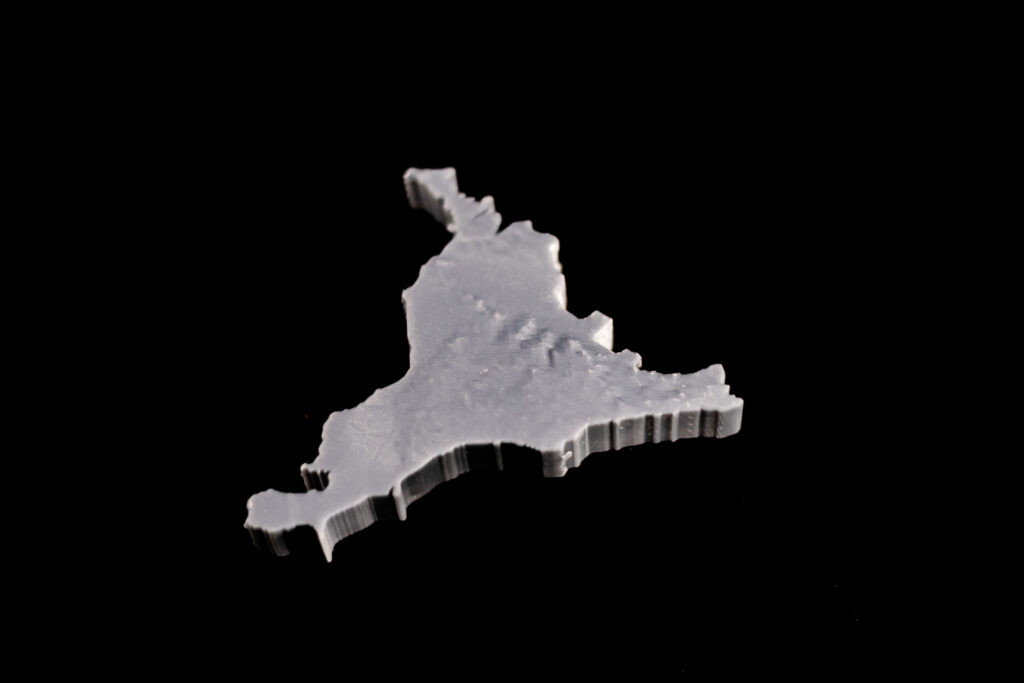
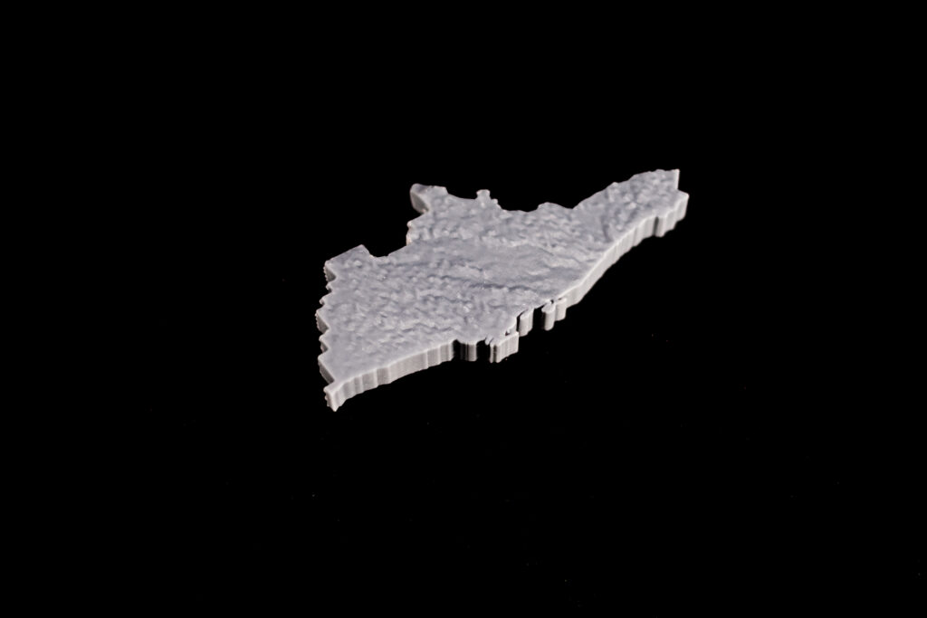
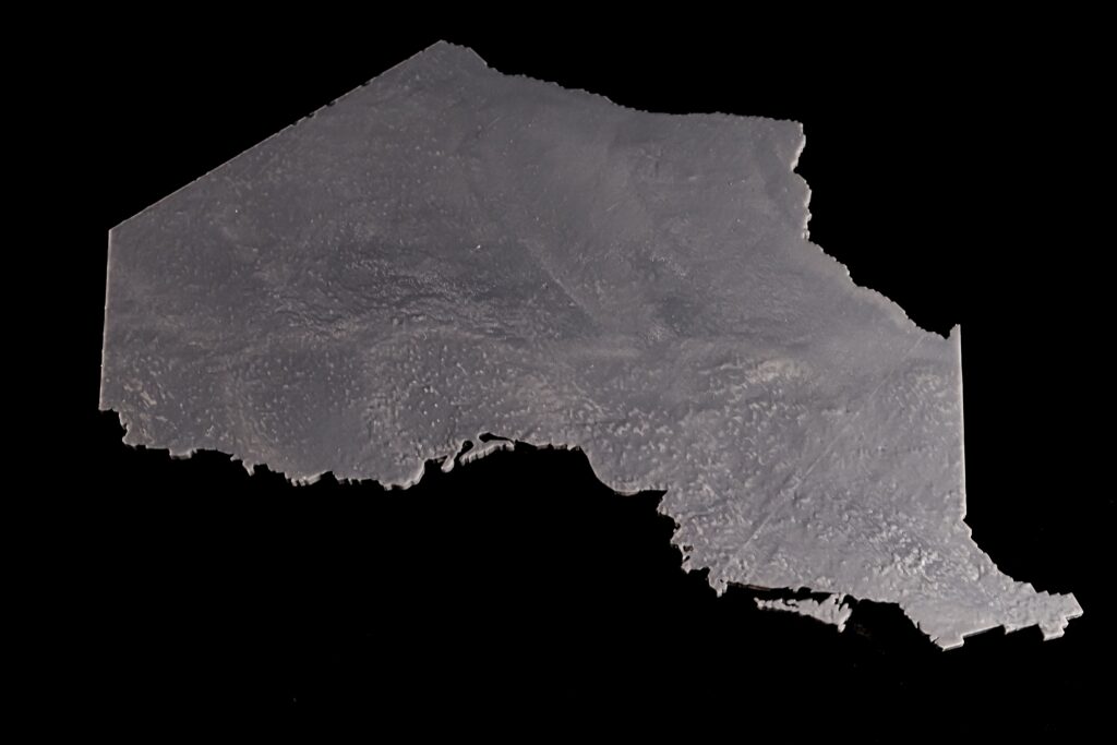
  • Converting a 3D Surface to a Solid: Materialise Magics – Converting surface to a solid with thickness and the model is cut according to the boundaries of the 5 Transitional Regions of Ontario. Using different thicknesses representing the differences in total population between Transitional Regions. (e.g. The central region has a population of 5 million, and the thickness is 10 mm; the west region has a population of 4 million the thickness is 8 mm)
  • Slicing & Printing: This step is an indispensable step for 3D printing, but because of the wide variety of printer brands on the market, most of them have their own slicing software developed by the manufacturers, so the specific operation process varies. But there is one thing in common, after this step, the file will be transferred to the 3D printer, and what follows is a long wait.

Visualization

The 5 Transitional Regions is reorganized by the 14 Local Health Integration Network (LHIN), and the corresponding population and model heights (thicknesses) for each of the five regions of Ontario are:

  • West, clustering of: Erie-St. Clair, South West, Hamilton Niagara Haldimand Brant, Waterloo Wellington, has a total population of about 4 million, the thickness is 8mm.
  • Central, clustering of: Mississauga Halton, Central West, Central, North Simcoe Muskoka, has a total population of about 5 million, the thickness is 10mm.
  • Toronto, clustering of: Toronto Central, has a total population of about 1.4 million, the thickness is 2.8mm.
  • East, clustering of: Central East, South East, Champlain, has a total population of about 3.7 million, the thickness is 7.4mm.
  • North, clustering of: North West, North East, has a total population of about 1.6 million, the thickness is 3.2mm.
Different thicknesses
Dimension Comparison
West region
Central region
Toronto
East region
North region

Limitations

The most unavoidable limitation of 3D printing is the accuracy of the printer itself. It is not only about the mechanical performance of the printer, but also about the materials used, the operating environment (temperature, UV intensity) and other external factors. The result of these factors is that the printed models do not match exactly, even though they are accurate on the computer. On the other hand, the 3D printed terrain can only represent variables that can be presented by unique values, such as the total population of my choice.

Toronto’s Rapid Transit System Throughout the Years, 1954 to 2030: Creating an Animated Map on ArcGIS Pro

Johnson Lumague

Geovis Project Assignment @RyersonGeo, SA8905, Fall 2022

Background

Toronto’s rapid transit system has been constantly growing throughout the decades. This transit system is managed by the Toronto Transit Commission (TTC) which has been operating since the 1920s. Since then, the TTC has reached several milestones in rapid transit development such as the creation of Toronto’s heavy rail subway system. Today, the TTC continues to grow through several new transit projects such as the planned extension of one of their existing subway lines as well as by partnering with Metrolinx for the implementation of two new light rail systems. With this addition, Toronto’s rapid transit system will have a wider network that spans all across the city.

Timeline of the development of Toronto’s rapid transit system

Based on this, a geovisualization product will be created which will animate the history of Toronto’s rapid transit system and its development throughout the years. This post will provide a step-by-step tutorial on how the product was created as well as showing the final result at the end.

Continue reading Toronto’s Rapid Transit System Throughout the Years, 1954 to 2030: Creating an Animated Map on ArcGIS Pro

Using ArcGIS Experience Builder for 3D Mapping of Zoning restrictions and Buildings in Toronto

Daniel Kogan

Geovis Project Assignment @RyersonGeo, SA8905, Fall 2021

Introduction/ background

Every city has zoning bylaws that dictate land use. Most cities, including the City of Toronto, have zoning bylaws that set building height limits for different zoning areas. Sometimes, buildings are built above the height limit, either due to development agreements or grandfathering of buildings (when a new zoning by-law doesn’t apply to existing buildings). The aim of this project is to provide a visualization tool for assessing which buildings in Toronto are within the zoning height limits and which are not.

Data and Processing

3D Buildings

The 3D building data was retrieved from Toronto Open Data and derived using the following methods:

  • LiDAR (2015)
  • Site Plans – building permit site plan drawings
  • Oblique Aerials – oblique aerial photos and “street view” photos accessible in Pictometry, Google Earth, and Google Maps.
  • 3DMode – digital 3D model provided by the developer

Zoning Bylaws

Two zoning Bylaw shapefiles were used (retrieved from Toronto Open Data as well):

  • Building Heights Limits – spatially joined (buildings within zoning area) to the 3D buildings to create the symbology shown on the map. Categories were calculated using the max average building height (3D data) and zoning height limit (zoning bylaws).
  • Zoning Categories – used to gain additional information and investigate how or why buildings went over the zoning height limit.

Geovisualization

ArcGIS experience builder was used to visualize the data. A local scene with the relevant data was uploaded as a web scene and chosen as the data source for the interactive map in the “Experience”. The map includes the following aspects: Legend showing the zoning and height categories, a layer list allowing users to toggle the zoning category layer on to for further exploration of the data, and a “Filter by Height Category” tool that allows users to view buildings within a selected height category. Pop-ups are enabled for individual buildings and zones for additional information. Some zones include bylaw expectations which may explain why some of the buildings within them are allowed to be above the zoning height limit (only an exception code is provided, a google search is required to gain a better understanding). instructions and details about the map are provided to the user as well.

Limitations

The main limitation of this project is insufficient data – a lack of either building height or zoning height results in a category of “No data” which are displayed as grey buildings. Another limitation is possibly the accuracy of the data, as LiDAR data can sometimes be off and provide wrong estimates of building height. Inaccuracies within 1m were solved by adding an additional category, but there may be some inaccuracies beyond

Under Construction Commercial Real Estate in Toronto Market

GeoVis Project @RyersonGeo, SA8905, Fall 2021, Mirza Ammar Shahid

Introduction

Commercial real estate is crucial part of the economy and is a key indicator of a region’s economic health. In the project different types of Under constriction projects within the Toronto market will be assessed. Projects that are under construction or are proposed to be completed within the next few years will be visualized. Some property types that will be looked at are, hospitality, office, industrial, retail, sports and entertainment etc. The distribution of each property type within the regions will be displayed. To determine the proportional distribution within each region by property type. Software that will be used is Tableau to create a visualization of the data which will be interactive to explore different data filters.

Data

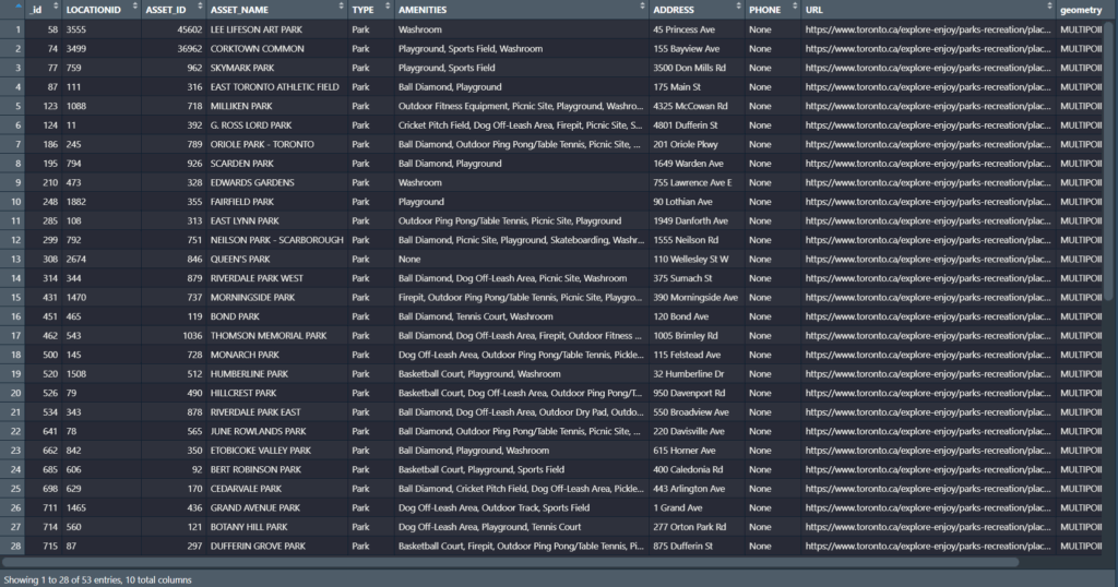
The data for the project was obtained from the Costar group’s database. The data used was exported using all properties within the submarket of Toronto (York region, Durham region, Peel Region, Halton region). Under construction or proposed properties above the size of 7000 sqft were exported to be used for the analysis. Property name, address, submarket, size, longitude, latitude and the year built were some of the attributes exported for each property project.

Method

  1. Once data was filtered and exported from the source, the data was inserted into Tableau as an excel file.
  2. The latitude and longitude were placed in rows and columns in order to create a map in tableau for visualization.
  3. Density of mark was used to show the density and a filter was applied for property type.
  4. Second sheet was created with same parameters but instead of density circle marks were used to identify locations of each individual project (Under Construction Projects).
  5. Third sheet was created with property type on x axis and proportion of each in each region in y axis. To show the proportions of each property type by region.
  6. The three worksheets were used to compile an interactive dashboard for optimal visualization of the data.
Figure 1: rows, columns and marks

Results

Density Map Showing Industrial Property type
All Under construction project locations
Regional Distribution by Property type

The results are quite intriguing as to where certain property type constriction dominant over the rest. Flex is greatest in Peel region, Health care in Toronto, Hospitality in Halton, Industrial in Peel, Multifamily in Toronto, Office in downtown Toronto, retail in York region, specialty in York region and sports and entertainment in Durham with new casino opening in Ajax.

The final dashboard can be seen below, however due to sharing restrictions, the dashboard can only be accessed if you have a Tableau account.

Click here to view dashboard

Conclusion

In conclusion, using under construction commercial real estate dashboard can have positive impact on multiple entities within the sector. Developers can use such geo visualizations to monitor ongoing projects and find new projects within opportunity zones. Brokerages can use this to find new leads, potential listings and manage exiting listings. Governments of all three levels, municipal, provincial and federal can use these dashboard to monitor health conditions of their constituency and make insightful policy changes based on facts.

Toronto Maple Leafs Game-Day Guide

Author: Olivia Kariunas

Geovisualization Project Assignment @RyersonGeo, SA8905, Fall 2021

Project Link: https://arcg.is/1Xr9i52

Background

The inspiration behind creating this geovisualization project stems from my own curiosity about Toronto’s tourism industry and love of the hometown hockey team. There have been numerous instances where I found myself stressed and anxious about planning a stay within Toronto due to the overwhelming number of options for every element of my stay. I wanted to create content in an interactive manner that would reduce the scope of options in terms of accommodations, restaurants, and other attractions in a user-friendly way. With a focus on attending a Toronto Maple Leafs game, I have created an interactive map that presents readers with hotels, restaurants and other attractions that are highly reviewed, along with additional descriptions that may provide useful to those going to these places for the first time. Each of these locations are located under 1 kilometer from the Scotiabank Arena to ensure that patrons will not require extensive transportation and can walk from venue to venue. Also, the intent behind the interactive map is to increase fan engagement by helping fans find a sense of community within the selected places and ease potential stressors of planning their stay. For a Toronto Maple Leafs fan, the fan experience starts before the game even begins.

Why Story Map?

Esri’s Story Map was chosen to conduct this project because it is a free user-friendly method that allows anyone with an Esri Online account to create beautiful stories to share with the world. By creating a free platform, any individual or business can harness the benefits of content creation for their own personal pleasure or for their small business. Furthermore, the Shortlist layout was chosen to include images and descriptions about multiple locations for the Story Map to give readers visual cues of the locations being suggested. The major goal behind using this technology is to ensure that individuals in any capacity can access and utilize this platform by making it accessible and easy to understand.

Data

To obtain the data for the specific locations of the hotels, restaurants, and other attractions, I inspected various travel websites for their top 10 recommendations. From these recommendations, I selected commonalities among the sites and included other highly recommended venues to incorporate diversity among the selection. For the selected hotels, I attempted to include various category levels to accommodate different budgets of those attending the Leafs game. Additionally, all attractions chosen do require an additional purchase of tickets or admission, but vary in price point as well.

Creating Your Story Map

Start the Story Map Shortlist Builder using a free ArcGIS public account on ArcGIS Online.

Create a title for your interactive map under the “What do you want to call your Shortlist?”. Try to be as creative, but concise, as possible!

The main screen will now appear. You can now see your title on the top left, as well as a subtitle and tabs below. To the right, there is a map that you can alter as you like. To add a place, click the “Add” button within the tab frame. This will allow you to create new places that you want to further describe.

Story Map Project Main Screen

A panel will appear where you can enter the name of the chosen destination, provide a picture, include text, and specify its location. You can include multiple images per tab using the “Import” feature. Once the location has been specified using the venue’s address, a marker will appear on the map. You are able to click and drag this marker to any destination that you choose. The colour of the marker correlates to the colour of the tab. Additionally, you can include links within the description area to redirect readers to the respective venue’s website.

Completed location post with title, image, and description.

Click the “+” button on the top right hand corner of the left side panel to add more destinations. The places that you add will show as thumbnails on the left side of the screen. Click the “Organize” button underneath the tab to reorder the places. You can order these in any way that seems logical for your project. Click “Done” when satisfied.

To create multiple tabs, click the “Add Tab” button. To edit a tab, click the “Edit Tab” button. This will allow you to change the colour of the tab and its title.

The Edit, Add, and Organize Tabs can be found to the right of the other tabs and above the map.

To save your work, press the “Save” button occasionally, so all of your hard work is preserved.

There are also optional elements that you can include as well. You can change the behaviour and appearance of your Shortlist by clicking the “Settings” button. You are able to change the various functions people can utilize on the map. This includes implementing a “Location Button” and “Feature Finder” where readers can see their own location on the map and find specific locations on the map, respectively. You are also able change the colour scheme and header information by clicking on their tab options. Hit “Apply” when satisfied.

Settings options tab

To share your Shortlist click the “Save” button and then click the “Share” button. You can share publicly or just within your organization. Additionally, you can share using a url link or even embed the Story Map within a website.

Final output of content

Limitations & Future Work

The main limitation of this project was selecting what venues to include. Toronto is a lively city with an overwhelming amount of options for visitors to choose from, resulting in many places being overlooked or unaccounted for. Overall, the businesses chosen represent a standard set of places for those who are unfamiliar with the city. To include a more diverse set of offerings, an addition to the current project, or an entirely new project, can be created to include places that provide more niche products/services. Furthermore, a large portion of the venues chosen were selected from travel/tourism advisory websites where the businesses on the sites may pay a fee to be included, thus limiting the amount of exposure other businesses may have.

Overall Thoughts

Story Map was simple to understand and the platform was aesthetically pleasing. My only reservations about this program is the limited amount of stylization control in terms of the text and other design elements. I would most likely use this platform again, but may attempt to find a technology that allows for more control over the overall appearance and settings of the geovisualization.

Thank you for reading my post. Have fun creating!

Tracking the COVID-19 Pandemic in Toronto with R and Leaflet

By: Tavis Buckland

Geovisualization Project Assignment, SA8905, Fall 2020

Github Repository: https://github.com/Bucklandta/TorontoCovid19Cases.git

INTRO

Over the course of the pandemic, the City of Toronto has implemented a COVID-19 webpage focused on providing summary statistics on the current extent of COVID-19 cases in the city. Since the beginning of the pandemic, this webpage has greatly improved, yet it still lacks the functionality to analyze spatio-temporal trends in case counts. Despite not providing this functionality directly, the City has released the raw data for each reported case of COVID-19 since the beginning of the pandemic . Using RStudio with the leaflet and shiny libraries, a tool was designed to allow for the automated collection, cleaning and mapping of this raw case data.

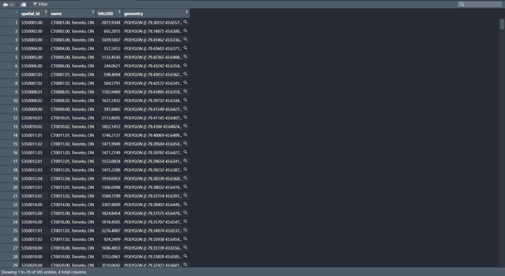
Sample of COVID-19 case data obtained from the Toronto Data Portal

DATA

The raw case data was downloaded from the Toronto Open Data Portal in R, and added to a data frame using read.csv. As shown in the image below, this data contained the neighbourhood name and episode date for each individual reported case. As of Nov. 30th, 2020, this contained over 38,000 reported cases. Geometries and 2016 population counts for the City of Toronto neighbourhoods were also gathered from the Toronto Open Data Portal.

PREPARING THE DATA

After gathering the necessary inputs, an extensive amount of cleaning was required to allow the case data to be aggregated to Toronto’s 140 neighbourhoods and this process had to be repeatable for each new instance of the COVID-19 case data that was downloaded. Hyphens, spaces and other minor inconsistencies between the case and neighbourhood data were solved. Approximately 2.5% of all covid cases in this dataset were also missing a neighbourhood name to join on. Instead of discarding these cases, a ‘Missing cases’ neighbourhood was developed to hold them. The number of cases for each neighbourhood by day was then counted and transposed into a new data table. From there, using ‘rowSum’, the cumulative number of cases in each neighbourhood was obtained.

Example of some of the code used to clean the dataset and calculate cumulative cases

Unfortunately, in its current state, the R code will only gather the most recent case data and calculate cumulative cases by neighbourhood. Based on how the data was restructured, calculating cumulative cases for each day since the beginning of the pandemic was not achieved.

CREATING A SHINY APP USING LEAFLET

Using leaflet all this data was brought together into an interactive map. Raw case counts were rated per 100,000 and classified into quintiles. The two screenshots below show the output and popup functionality added to the leaflet map.

In its current state, the map is only produced on a local instance and requires RStudio to run. A number of challenges were faced when attempting to deploy this map application, and unfortunately, the map was not able to be hosted through the shiny apps cloud-server. As an alternative, the map code has been made available through a GitHub repository at the top of this blog post. This repository also includes a stand-alone HTML file with an interactive map.

Screenshot of HTML map produced by R Shiny App and Leaflet. Popups display neighbourhood names, population, raw count, and rate per 100,000 for the most recent case data.

LIMITATIONS

There are a couple notable limitations to mention considering the data and methods used in this project. For one, the case data only supports aggregation to Toronto neighbourhoods or forward sortation areas (FSA). At this spatial scale, trends in case counts are summarized over very large areas and are not likely to accurately represent This includes the modifiable areal unit problem (MAUP), which describes the statistical biases that can emerge from aggregating real-world phenomena into arbitrary boundaries. The reported cases derived from Toronto Public Health (TPH) are likely subject to sampling bias and do not provide a complete record of the pandemic’s spread through Toronto. Among these limitations, I must also mention my limited experience building maps in R and deploying them onto the Shinyapps.io format.

FUTURE GOALS

With the power of R and its many libraries, there are a great many improvements to be made to this tool but I will note a few of the significant updates I would like to implement over the coming months. Foremost, is to use the ‘leaftime’ R package to add a timeline function, allowing map-users to analyze changes over time in reported neighbourhood cases. Adding the function to quickly extract the map’s data into a CSV file, directly from the map’s interface, is another immediate goal for this tool. This CSV could contain a snapshot of the data based on a particular time frame identified by a user. The last functionality planned for this map is the ability to modify the classification method used. Currently, the neighbourhoods are classified into quintiles based on cumulative case counts per 100,000. Using an extended library of leaflet, called ‘leafletproxy’, would allow map users greater control over map elements. It should be possible to allow users to define the number of classes and which method (i.e. natural breaks, standard deviation, etc.) directly from the map application.

The Toronto Financial Institution Market: Bridging the gap between Cartography and Analytics using Tableau

Nav Salooja

“Geovis Project Assignment @RyersonGeo, SA8905, Fall 2019”

<script type='text/javascript' src='https://prod-useast-a.online.tableau.com/javascripts/api/viz_v1.js'></script><div class='tableauPlaceholder' style='width: 1920px; height: 915px;'><object class='tableauViz' width='1920' height='915' style='display:none;'><param name='host_url' value='https%3A%2F%2Fprod-useast-a.online.tableau.com%2F' /> <param name='embed_code_version' value='3' /> <param name='site_root' value='/t/torontofimarketgeovisprojectsa8905fall2019' /><param name='name' value='TheTorontoFIMarketDashboard/TorontoFIMarket' /><param name='tabs' value='yes' /><param name='toolbar' value='yes' /><param name='showAppBanner' value='false' /></object></div>

Introduction & Background

Banking in the 21st century has evolved significantly especially in the hyper competitive Canadian Market. Big banks nationally have a limited population and wealth share to capture given Canada’s small population and have been active in innovating their retail footprint. In this case study, TD Bank is the point of interest given its large branch network footprint in the Toronto CMA. Within the City of Toronto the bank has 144 branches and is used as the study area for the dashboard created.  The dashboard analyzes the market potential, branch network distribution, banking product recommendations and client insights to help derive analytics through a centralized and interactive data visualization tool.

Technology

The technology selected for the geovisualization component is Tableau given its friendly user interface, mapping capabilities, data manipulation and an overall excellent visualization experience. However, Alteryx was widely used for the build out of the datasets that run in Tableau. As the data was extracted from various different sources, spatial element and combining datasets was all done in Alteryx. The data extracted for Expenditure, Income and Dwelling Composition was merged and indexed in Alteryx. The TD Branches was web scrapped live from the Branch Locator and the trading areas (1.5KM Buffers) are also created in Alteryx. The software is also used for all the statistical functions such as the indexed data points in the workbook were all created in Alteryx. The geovisualization component is all created within the Tableau workbooks as multiple sheets are leverged to create an interactive dashboard for full end user development and results.
Figure 1 represents the Alteryx Workflow used to build the Market, Branch and Trade Area datasets
Figure 2 provides the build out of the final data sets to fully manipulate the data to be Tableau prepared

Data Overview

There are several data sets used to build the multiple sheets in the tableau workbook which range from Environics Expenditure Data, Census Data and webscrapped TD branch locations. In addition to these data sets, a client and trade area geography file was also created. The clients dataset was generated by leveraging a random name and Toronto address generator and those clients were then profiled to their corresponding market. The data collected ranges from a wide variety of sources and geographic extents to provide a fully functional view of the banking industry. This begins by extracting and analyzing the TD Branches and their respective trade areas. The trading areas are created based on a limited buffer representing the immediate market opportunity for the respective branches. Average Income and Dwelling composition variables are then used at the Dissemination Area (DA) geography from the 2016 Census. Although income is represented as an actual dollar value, all market demographics are analyzed and indexed against Toronto CMA averages. As such these datasets combined with Market, Client and TD level data provide the full conceptual framework for this dashboard.
Tables & Visualization Overview

Given the structure of the datasets, six total tables are utilized to combine and work with the data to provide the appropriate visualization. The first two tables are the branch level datasets which begin with the geographic location of the branches in the City of Toronto. This is a point file taken from the TD store locator with fundamental information about the branch name and location attributes. There is a second table created which analyzes the performance of these branches in respect to their client acquisition over a pre-determined timeframe.

Figure three is a visualization of the first table used and the distribution of the Branch Network within the market

The third table used consists of client level information selected from ‘frequent’ clients (clients transacting at branches 20+ times in a year. Their information builds on the respective geography and identifies who and where the client resides along with critical information that is usable for the bank to run some level of statistical analytics. The client table shows the exact location of those frequent clients, their names, unique identifiers, their preferred branch, current location, average incomes, property/dwelling value and mortgage payments the bank collects. This table is then combined to understand the client demographic and wealth opportunity from these frequent clients at the respective branches.

Figure four is the visualization of the client level data and its respective dashboard component

Table four and five are extremely comprehensive as they visualize the geography of the market (City of Toronto at a DA level). This provides a trade area market level full breakdown of the demographics and trading areas as DAs are attributed to their closest branch and allows users to trigger on for where the bank has market coverage and where the gaps reside. However, outside of the allocation of the branches, the geography has a robust set of demographics such as growth (population, income), Dwelling composition and structure, average expenditure and the product recommendations the bank can target driven through the average expenditure datasets. Although the file has a significant amount of data and can be seen as overwhelming, selected data is fully visualized. This also has the full breakdown of how many frequent clients reside in the respective markets and what kind of products are being recomened on the basis of the market demographics analyzed through dwelling composition, growth metrics and expenditure.

Figure five is the visualization of the market level data and its respective dashboard component

The final table provides visualization and breakdown of the five primary product lines of business the bank offers which are combined with the market level data and cross validated against the average expenditure dataset. This is done to identify what products can be recommended throughout the market based on current and anticipate expenditure and growth metrics. For example, markets with high population, income and dwelling growth with limited spend would be targeted with mortgage products given the anticipated growth and the limited spend indicating a demographic saving to buy their home in a growth market. These assumptions are made across the market based on the actual indexed values and as such every market (DA) is given a product recommendation.

Figure six is the visualization of the product recommendation and analysis data and its respective dashboard component

Dashboard

Based on the full breakdown of the data extracted, the build out and the tables leveraged as seen above, the dashboard is fully interactive and driven by one prime parameters which controls all elements of the dashboard. Additional visualizations such as the products visualization, the client distribution treemap and the branch trends bar graph are combined here. The products visualization provides a full breakdown of the products that can be recommended based on their value and categorization to the bank. The value is driven based on the revenue the product can bring as investment products drive higher returns than liabilities. This is then broken down into three graphs consisting of the amount of times the product is recommended, the market coverage the recommendation provides between Stocks, Mortgages, Broker Fees, Insurance and Personal Banking products. The client distribution tree map provides an overview by branch as to how many frequent clients reside in the branch’s respective trading area. This provides a holistic approach to anticipating branch traffic trends and capacity constraints as branches with a high degree of frequent clients would require larger square footage and staffing models to adequately service the dependent markets. The final component is the representation of the client trends in a five year run rate to identify the growth the bank experienced in the market and at a branch level through new client acquisition. This provides a full run down of the number of new clients acquired and how the performance varies year over year to identify areas of high and low growth.

This combined with the primary three mapping visualizations, creates a fully robust and interactive dashboard for the user. Parameters are heavily used and are built on a select by branch basis to dynamically change all 6 live elements to represent what the user input requires. This is one of the most significant capabilities of Tableau, the flexibility of using a parameter to analyze the entire market, one branch at a time or to analyze markets without a branch is extremely powerful in deriving insights and analytics. The overall dashboard then zooms in/out as required when a specific branch is selected highlighting its location, its respective frequent clients, the trade area breakdown, what kind of products to recommend, the branch client acquisition trends and the actual number of frequent clients in the market. This can also be expanded to analyze multiple branches or larger markets overall if the functionality is required. Overall, the capacity of the dashboard consists of the following elements:

1. Market DA Level Map
2. Branch Level Map
3. Client Level Map
4. Client Distribution (Tree-Map)
5. Branch Trending Graph
6. Product Recommendation Coverage, Value and Effectiveness

This combined with the capacity to manipulate/store a live feed of data and the current parameters used for this level of analysis bring a new capacity to visualizing large datasets and providing a robust interactive playground to derive insights and analytics.

The link for this full Tableau Workbook is hosted here (please note an online account is required):https://prod-useast-a.online.tableau.com/t/torontofimarketgeovisprojectsa8905fall2019/views/TheTorontoFIMarketDashboard/TorontoFIMarket?:showAppBanner=false&:display_count=n&:showVizHome=n&:origin=viz_share_link

Geovisualization of Crime in the City of Toronto Using Time-Series Animation Heat Map in ARCGIS PRO

Hetty Fu

Geovis Project Assignment @RyersonGeo, SA8905, Fall 2019

Background/Introduction

The City of Toronto Police Services have been keeping track of and stores historical crime information by location and time across the City of Toronto since 2014. This data is now downloadable in Excel and spatial shapefiles by the public and can be used to help forecast future crime locations and time. I have decided to use a set of data from the Police Services Data Portal to create a time series map to show crime density throughout the years 2014 to 2018. The data I have decided to work with are auto-theft, break and enter, robbery, theft and assault. The main idea of the video map I want to display is to show multiple heat density maps across month long intervals between 2014 to 2018 in the City of Toronto and focus on downtown Toronto as most crimes happen within the heart of Toronto.

The end result is an animation time-series map that shows density heat map snapshots during the 4-year period, 3-month interval at a time. Examples of my post are shown at the end of this blog post under Heat Map Videos.

Dataset

All datasets were downloaded through the Toronto Police Services Data Portal which is accessible to the public.

The data that was used to create my maps are:

  1. Assault
  2. Auto Theft
  3. Robbery
  4. Break and Enter
  5. Theft

Process Required to Generate Time-Series Animation Heat Maps

Step 1:  Create an additional field to store the date interval in ArcGis Pro.

Add the shapefile downloaded from the Toronto Police Services Portal intoArcGIS Pro.

First create a new field under View Table and then click on Add.             

To get only the date, we use the Calculate Field in the Geoprocessing tools with the formula

date2=!occurrence![:10]  

where Occurrence is the existing text field that contains the 10 digit date: YYYY-MM-DD. This removes the time of day which is unnecessary for our analysis.

Step 2: Create a layer using the new date field created.

Go into properties in the edited layer. Under the time tab, place in the new date field created from Step 1 and enter in the time extent of the dataset. In this case, it will be from 2014-01-01 to 2018-12-31 as the data is between 2014 to 2018.

Step 3: Create Symbology as Heat Map

Go into the Symbology properties for the edited layer and select heat map under the drop down menu. Select 80 as its radius which will show the size of the density concentration in a heat map. Choose a color scheme and set the method as Dynamic. The method used will show how each color in the scheme relates to a density value. In a Dynamic setting versus and constant, the density is recalculated each time the map scale or map extent changes to reflect only those features that are currently in view. The Dynamic method is useful to view the distribution of data in a particular area, but is not valid for comparing different areas across a map (ArcGIS Pro Help Online).

Step 4: Convert Map to 3D global scene.

Go to View tab on the top and select convert to global scene. This will allow the user to create a 3D map feature when showing their animated heat map.

Step 5: Creating the 3D look.

Once a 3D scene is set, press and hold the middle mouse button and drag it down or up to create a 3D effect.

Step 6: Setting the time-series map.

Under the Time tab, set the start time and end time to create the 3 month interval snapshot. Ensure that “Use Time Span” is checked and the Start and End date is set between 2014 and 2018. See the image below for settings.

Step 7: Create a time Slider Steps for Animation Purposes

Under Animation tab, select the appropriate “Append Time” (the transition time between each frame). Usually 1 second is good enough, anything higher will be too slow. Make sure to check off maintain speed and append front before Importing the time Slider Steps. See below image.

Step 8: Editing additional cosmetics onto the animation.

Once the animation is created, you may add any additional layers to the frames such as Titles, Time Bar and Paragraphs.

There is a drop down section in the Animation tab that will allow you to add these cosmetic layers onto the frame.

Animation Timeline by frames will look like this below.

Step 9: Exporting to Video

There are many types of exports the user can choose to create. Such as Youtube, Vimeo, Twitter, Instagram, HD1080 and Gif. See below image for the settings to export the create animation video. You can also choose the number of frames per second, as this is a time-series snapshot no more than 30 frames per second is needed. Choose a place where you would like to export the video and lastly, click on Export.

Conclusion/Recommendation/Limitation

As this was one of my first-time using ArcGIS Pro software, I find it very intuitive to learn as all the functions were easy to find and ready to use. I got lucky in finding a dataset that I didn’t have to format too much as the main fields I required were already there and the only thing required was editing the date format. The number of data in the dataset was sufficient for me to create a time series map that shows enough data across the city of Toronto spanning 3 months at a time. If there was less data, I would have to increase my time span. The 3D scene on ArcGIS Pro is very slow and created a lot of problems for me when trying to load my video onto set time frames. As a result of the high-quality 3D setting, I decided to use, it took couple of hours to render my video through the export tool. As the ArcGIS Pro software wasn’t made to create videos, I felt that there was lack of user video modification tools.

Heat Map Videos Export

  1. Theft in Downtown Toronto between 2014-2018. A Time-Series Heat Map Animation using a 3 month Interval.
  2. Robbery in Downtown Toronto between 2014-2018. A Time-Series Heat Map Animation using a 3 month Interval.
  3. Break and Enter in Downtown Toronto between 2014-2018. A Time-Series Heat Map Animation using a 3 month Interval.
  4. Auto Theft across the City of Toronto between 2014-2018. A Time-Series Heat Map Animation using a 3 month Interval.
  5. Assault across the City of Toronto between 2014-2018. A Time-Series Heat Map Animation using a 3 month Interval.