Mapping Toronto’s Post-War Urban Sprawl & Infill Growth (1945-2021)

A Geovizualization Project by Mandeep Rainal.

SA8905 – Master of Spatial Analysis, Toronto Metropolitan University.

For this project, I explore how Toronto has grown and intensified over time, by creating a 3D animated geovisualization using Kepler.gl. I will be using 3D building massing data from the City of Toronto and construction period information from the 2021 Census data (CHASS).

Instead of showing a static before and after map, I decided to build a 3D animated geovizualization that reveals how the city “fills in” over time showing the early suburban expansion, mid-era infill, and rapid post-2000 intensification.

To do this, I combined the following:

  • Toronto’s 3D Massing Building Footprints
  • Age-Class construction era categories
  • A Custom “Built-Year” proxy
  • A timeline animation created in Kepler. gl and Microsoft Windows.

The result is a dynamic sequence showing how Toronto physically grew upward and outward.

BACKGROUND

Toronto is Canada’s largest and fastest growing city. Understanding where and when the built environment expanded helps explain patterns of suburbanization, identify older and newer development areas and see infill and intensification. This also helps contextualize shifts in density and planning priorities for future development.

Although building-level construction years are not publicly available, the City of Toronto provides detailed 3D massing geometry, and Statistics Canada provides construction periods at the census tract level for private dwellings.

By combining these sources into a single animated geovizualization, we can vizualize Toronto’s physical growth pattern over 75 years.

DATA

  • City of Toronto – 3D Building Massing (Polygon Data)
    1. Height attributes (average height)
    2. Building Footprints
    3. Used for 3D extrusions
  • City of Toronto – Muncipal Boundary (Polygon Data)
    1. Used to isolate from the Census metropolitan area to the Toronto city core.
  • 2021 Census Tract Boundary
  • CHASS (2021 Census) – Construction Periods for Dwellings
    1. Total dwellings
    2. 1960 and before
    3. 1961-1980
    4. 1981-1990
    5. 1991-2010
    6. 2011-2015
    7. 2016-2021
    8. Used to assign Age classes and a generalized “BuiltYear” for each building.

METHODOLOGY

Step 1: Cleaning and Preparing the Data in ArcGIS Pro

  • I first imported the collected data into ArcGIS. I clipped the census tract layers to the City of Toronto boundary to get census tracts for Toronto only.
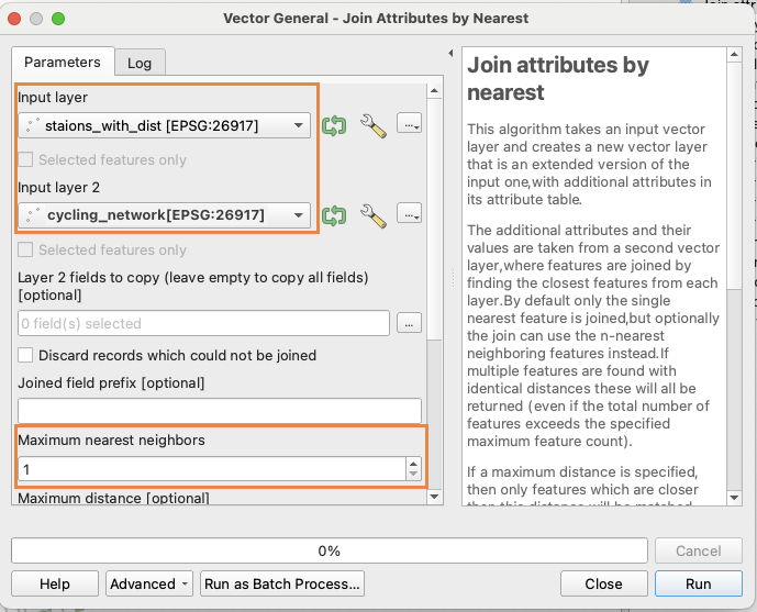
  • Next, I joined the census tract polygon layer we created to the construction period data that was imported. This gives us census tracts with construction period counts.
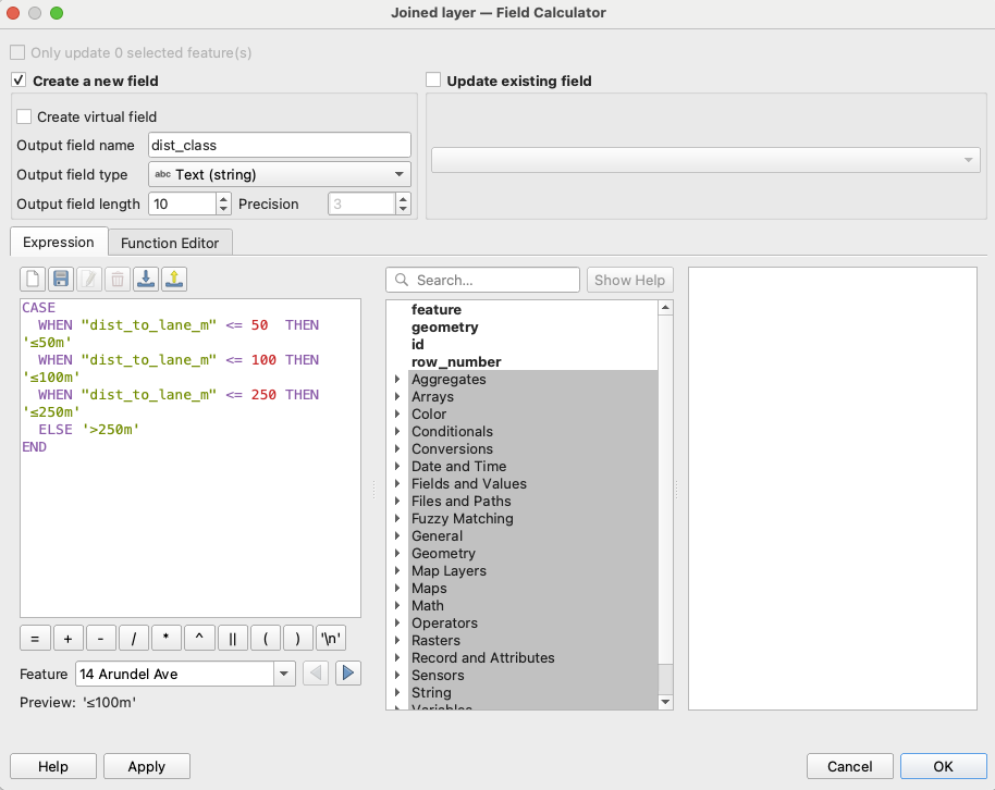
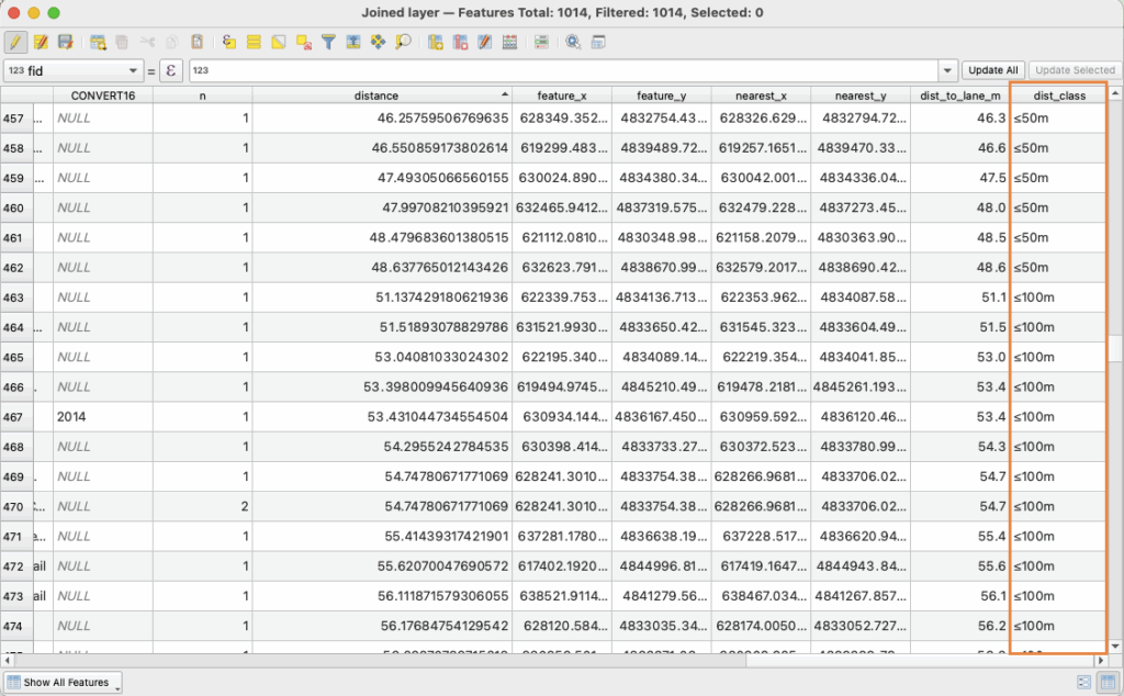
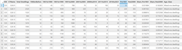
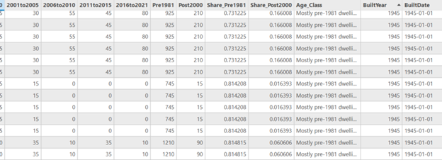
  • Because Toronto does not have building-year data, I assigned construction era categories from the census as proxies for building age, and created an age classification system using proportions. Adding periods and dividing / total dwellings to get proportions, and assigned them into three classes:
    • Mostly Pre-1981 dwellings
    • Mixed-era dwellings
    • Mostly 2000+dwellings
  • Next, I needed a numeric date field for Kepler to activate the time field. I assigned a representative year to each tract using the Age classes.
    • if age = Mostly Pre-1981 dwellings = 1945
    • if age = Mixed-era dwellings = 1990
    • if age = Mostly 2000+dwellings = 2010
  • And to make the built year Kepler-compatible a new date field was created to format as 1945-01-01.
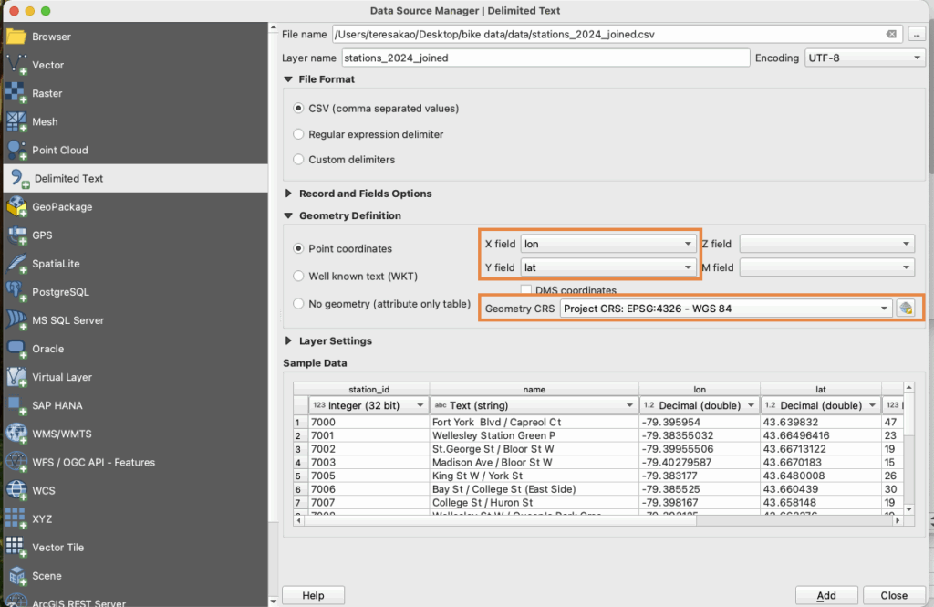
  • The data was then exported as GeoJSON files to import into Kepler.gl. The built year data was also exported as a CSV because Kepler doesn’t pick up on the time field in geoJSON easily.

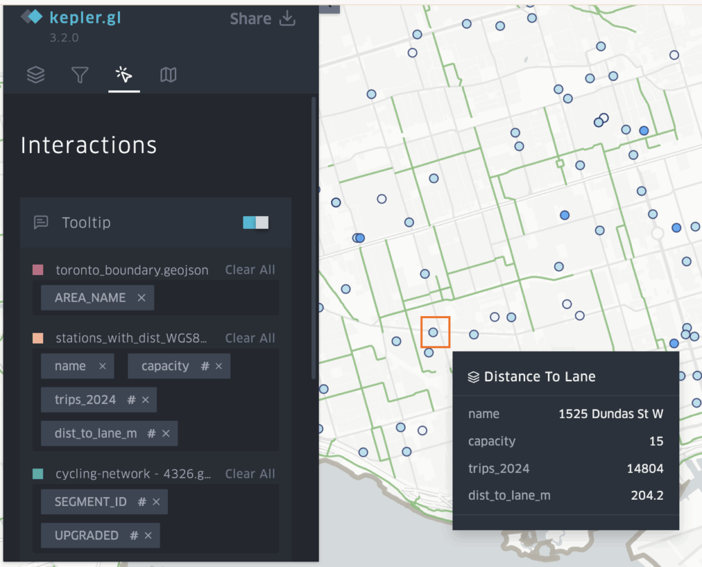
Stage 2: Visualizing the Growth in Kepler

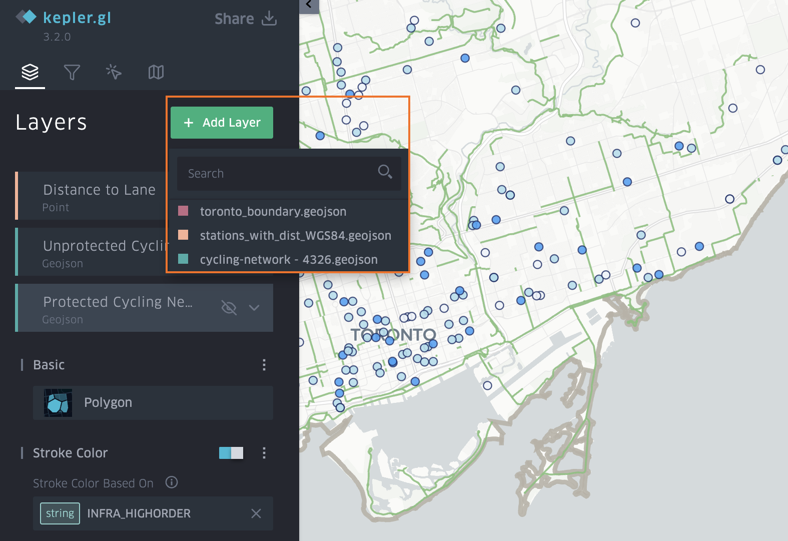
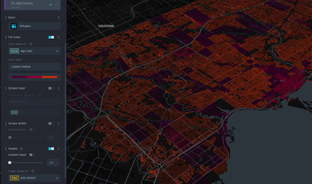
  • Once the layers are loaded into Kepler the tool allows you manipulate and vizualize different attributes quickly.
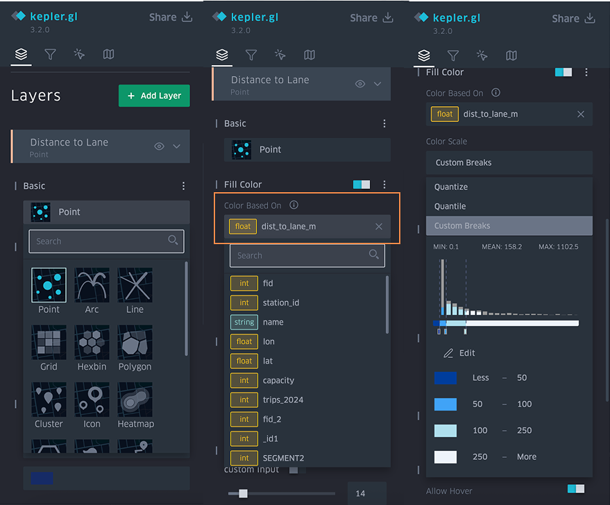
  • First the 3D Massing GeoJSON was set to show height extrusion based on the average height field. The colour of the layer was muted and set to be based on the age classes and dwelling eras of the buildings.
  • Second layer, was a point layer also based on the age-classes. This would fill in the 3D massings as the time slider progressed, and was based on brighter colours.
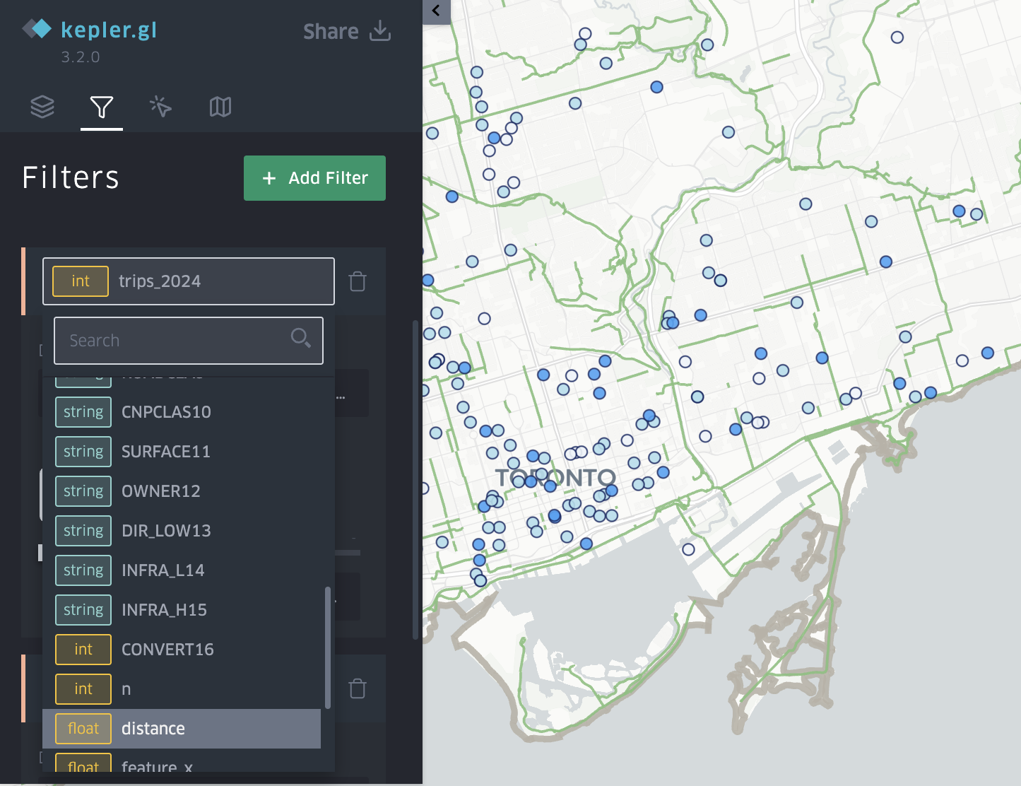
  • The Built Date CSV was added as a time-based filter for the build date field.

The final visualization was screen recorded and shows an animation of Toronto being built from 1945 to 2021.

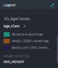
  • Teal = Mixed-era dwellings
  • Amber = Mostly 2000+ dwellings
  • Dark purple = Mostly Pre-1981 dwellings

RESULTS

The animation reveals key patterns on development in the city.

  • Pre-1981 areas dominate older neighbourhoods, the purple shaded areas show Old Toronto, Riverdale, Highpark, North York.
  • Mixed-era dwellings appear in more transitional suburbs, filling in teal, and showing subdividisions with infill.
  • Mostly 2000+ dwellings are filling in amber and highlight the rapid intensification in areas like downtown with high-rise booms, North York centre, Scarborough Town Centre.

The animation shows suburban sprawl expanding outward, before the vertical intensification era begins around the year 2000.

Because Kepler.gl cannot export 3D time-slider animations as standalone HTML files, I captured the final visualization using Microsoft Windows screen recording instead.

LIMITATIONS

This visualization used census tract–level construction-period data as a proxy for building age, which means the timing of development is generalized rather than precise. I had to collapse the CHASS construction ranges into age classes because the census periods span multiple decades and cannot be animated in Kepler.gl’s time slider, which only accepts a single built-year value per feature. Because all buildings within a tract inherit the same age class, fine-grained variation is lost and the results are affected by aggregation. Census construction categories are broad, and assigning a single representative “built year” further simplifies patterns. The Kepler animation therefore illustrates symbolic patterns of sprawl, infill, and intensification, not exact chronological construction patterns.

CONCLUSION

This project demonstrates how multiple datasets can be combined to produce a compelling 3D time-based visualization of a city’s growth. By integrating ArcGIS Pro preprocessing with Kepler’s dynamic visualization tools, I was able to:

  • Simplify census construction-era data
  • Generate meaningful urban age classes
  • Create temporal building representations
  • Visualize 75+ years of urban development in a single interactive tool

Kepler’s time slider adds an intuitive, animated story of how Toronto grew, revealing patterns of change that static maps cannot communicate.

Spatial Accessibility and Ridership Analysis of Toronto Bike Share Using QGIS & Kepler.gl

Teresa Kao

Geovis Project Assignment, TMU Geography, SA8905, Fall 2025

Hi everyone, in this project, I explore how cycling infrastructure influences Bike Share ridership across Toronto. Specifically, I examine whether stations located within 50 meters of protected cycling lanes exhibit higher ridership than those near unprotected lanes, and to see which areas protected cycling lanes could be improved.

This tutorial walks through the full workflow using QGIS for spatial analysis and Kepler.gl for interactive mapping, filtering, and data exploration. By the end, you’ll be able to visualize ridership patterns, measure proximity to cycling lanes, and identify where additional stations or infrastructure could improve accessibility.

Preparing the Data in QGIS

Importing Cycling Network and Station Data

Import the cycling network shapefiles using Layer -> Add Layer -> Add Vector Layer, and load the Bike Share station CSV by assigning X = longitude, Y = latitude, and setting the CRS to EPSG:4326 (WGS84).

Reproject to UTM 17N for Distance Calculations

Because Kepler.gl only supports GeoJSON in EPSG:4326, all layers are first reprojected in QGIS to EPSG:26917 (Right click -> Export -> Save Features As…), distance calculations are performed there, and the processed results are then exported back to GeoJSON (EPSG:4326) for use in Kepler.gl.

Calculating Distance to the Nearest Cycling Lane

Use the Join Attributes by Nearest tool ( Processing Toolbox-> Join Attributes by Nearest), setting the Input Layer to stations dataset, the Join Layer to the cycling lane dataset, and Maximum neighbours to 1. This will generate an output layer with a new field (distance_to_lane_m) representing the distance in meters from each station to its nearest cycling lane.

Creating Distance Categories

Use the Field Calculator (∑) to create distance classifications using the following expression :

<CASE
WHEN "dist_to_lane_m" <= 50 THEN '≤50m'
WHEN "dist_to_lane_m" <= 100 THEN '≤100m'
WHEN "dist_to_lane_m" <= 250 THEN '≤250m'
ELSE '>250m'
END>

Exporting to GeoJSON for Kepler.gl

Since Kepler.gl does not support shapefiles, export each layer as a GeoJSON (Right Click -> Export -> Save Features As -> Format: GeoJSON -> CRS: EPSG:4326). The distance values will remain correct because they were already calculated in UTM projection.

Building Interactive Visualizations in Kepler.gl

Import Data

Go to Layer -> Add Layer -> choose data

  1. For Bike Share Stations, use the point layer and symbolize it by the distance_to_lane_m field, selecting a colour scale and applying custom breaks to represent different distance ranges.
  2. For Protected Cycling Network, use the polygon layer and symbolize it by all the protected lane columns, applying a custom ordinal stroke colour scale such as light green.
  3. For Unprotected Cycling Network, use the polygon layer and symbolize it by all the unprotected columns, applying a custom ordinal stroke colour scale such as dark green.
  4. For Toronto Boundary, use the polygon layer and assign a simple stroke colour to outline the study area.

Add Filters

The filter slider is what makes this visualization powerful. Go to Add Filter -> Select a Dataset -> Choose the Field (for example ridership, distance_to_lane)

Add Tooltips

Go to Tooltip -> Toggle ON -> Select fields to display. Enable tooltips so users can hover a station to see details, such as station name, ridership, distance to lane, capacity.

Exporting Your Interactive Map

Export image, table(csv), and map (shareable link) -> uses Mapbox Api to create an interactive online map that other people can interact with your map.

How this interactive map help answer the research question

This interactive map helps answer the research question in two ways.
First, by applying a filter on distance_to_lane_m, users can isolate stations located within 50 meters of a cycling lane and visually compare their ridership to stations farther away. Toggling between layers for protected and unprotected cycling lanes allows users to see whether higher ridership stations tend to cluster near protected infrastructure.

Based on the map, the majority of higher ridership stations are concentrated near protected cycling lanes, suggesting a positive relationship between ridership and proximity to safer cycling infrastructure.

Second, by applying a ridership filter (>30,000 trips), the map highlights high demand stations that lack nearby protected cycling lanes. These appear as busy stations located next to unprotected lanes or more than 50 meters away from any cycling facility.

Together, these filters highlight where cycling infrastructure is lacking, especially in the Yonge Church area and the Downtown East / Yonge Dundas area, making it clear where protected lanes may be needed.

Final Interactive Map

Thank you for taking the time to explore my blog. I hope it was informative and that you were able to learn something from it!

Visualizing New York City yellow cabs and their origin-destination over time

Fana Gidey
SA8905 – Cartography and Geovisualization
Fall 2019
@Ryersongeo

Background

Taxi networks can uncover how people move within neighbourhoods and detect distinct communities, cost of housing and other socio-economic features.  New York City is famous for its yellow cabs and diverse neighbourhoods providing a good study area. This project will look at trip records for Yellow Cab taxi’s in order to visualize New York residents travel patterns over-time.

On New Year’s Eve, New York taxi riders are expected to make their way to see the ball drop, watch the fireworks from the east of Hudson River, Battery Park, and Coney Island. Lastly movement from the outer boroughs into Manhattan and Brooklyn for entertainment is expected. 

Marketers, policy makers, urban planners and real estate industry can leverage this spatial data to predict activity and features of human society.

Technology

The technology used for visualization is Kepler.gl. Kepler.gl is an open-source geospatial data analysis tool. I picked the tool because it can visualize paths over time with time-series and animations that can communicate a very powerful data narrative. Previous examples were flight and refugee movement data. Kepler has drag and drop options to highly skilled scripting.

Step 1: Gathering the Data

The data was obtained NYC Open Data Portal – Transportation – City of New York. Here you can obtain Yellow, Green Cab and For-Hire Vehicle trip records. Initially I wanted to compare trip records between two years (i.e. 2009 and 2016) however this data set is so robust (131,165,043 records). I decided to narrow down and focused on yellow cabs and only a single date that may have lots of taxi activity (January 1st 2016). The columns in the data set include: VendorID, Pickup and Drop-off Date Timestamp, pickup and drop off latitude and longitudes, trip distance, payment type, payment amount, tax, toll amount, and total amount.

Step 2: Cleaning the Data

It is imperative to know how data needs to be structured when drawing paths over time using origin-destination data. In order to create a path over time map, the data source should include the following types of information:

  • The Latitude and Longitude coordinates for each trip data point in a path
  • A column that defines the order to connect the points (in my case I used the date timestamp information, or you can manually applied surrogate key is also acceptable (i.e. 1, 2, 3, 4, 5)
  • The source data has a sufficient amount of data points to create lines from points

Before

The data was then cleaned and prepped for use in excel. The fields were formatted to currency (2 decimal spaces $) date (m/d/yyyy h:mm:ss) and null values were removed. A trip duration field was calculated and obsolete data is removed. The csv now has 345,038 records.

After

Step 3: Create Visualization

Now that that the data is cleaned and prepped for use it can be implemented to an interactive visualization software. As soon as you navigate to kepler.gl and select ‘Get Started’. You will be prompted to add your data (i.e. csv, json, and geojson).

Once your data is loaded, you can start with the “Layer” options. The software was able to pick up the pick-up and drop-off latitude and longitude. The pick-up and drop-off are represented as point features, you can use the drop-down menu to select lines, arcs, etc.

The origin-destination points are now represented by arcs. In order to animate the feature, a field must be selected to sort by.

In the filters tab, you can choose a field to sort by (i.e. “pick_up datetime”).

You can edit the map style by select the “Base Map” tab.

Other customization features are highlighted below.

Final Results

https://fanagidey.github.io/

Create a Quick Web Map with Kepler.gl and Jupyter Notebook

Author: Jeremy Singh

SA8903

GeoVisualization Project Fall 2019

Background: This tutorial uses any csv file with latitude and longitude columns in order to plot points on the web map. Make sure your csv file is saved in the same folder this notebook is saved (makes things easier).

I recommend downloading the Anaconda Distribution which comes with jupyter notebook.

There are 3 main important python libraries that are used in this tutorial

  1. Pandas: Pandas is a python library that is used for data analysis and manipulation.
  2. kepler.gl: This a FREE open-source web-based application that is capable of handling large scale geospatial data to create beautiful visualizations.
  3. GeoPandas: Essentially, geopandas is an extension of Pandas; fully capable of handling and processing of geospatial data.

The first step is to navigate to the folder where you want this notebook to be saved from the main directory when juypter notebook is launched. Then click ‘new’ -> Python 3, a tab will open up with your notebook (See image below).

Next, using the terminal it is important to have these libraries installed to ensure that this tutorial works and everything runs smoothly.

For more information on jupyter notebook see: https://jupyter.org/

Navigate back to the directory and open a terminal prompt via the ‘new’ Tab’.

A new tab will open up, this will function very similarly to the command prompt on windows. Next type “pip install pandas keplergl geopandas” (do not include quotes). This process will help install these libraries.

Below you will find what my data looks like the map before styling

With some options

KeplerGL also allows for 3D visualizations. Here is my final map:

Lastly, if you wish to save off your web map as an HTML file to host somewhere like GitHub or AWS this command will do that for you:

Link to my live web map here:

https://jeremysingh21.github.io/

The code and data I used for this tutorial is located on my GitHub page located here:

https://github.com/jeremysingh21/GeoVizJeremySingh

Time-series Animation of Power Centre Growth in the Greater Toronto Area for the Last 25 Years

By: Jennifer Nhieu
Geovisualization Class Project @RyersonGeo, SA8905, Fall 2018

Introduction:

In 1996, there were 29 power centres with 239 retail tenants accounting for just under five million square feet of retail space (Webber and Hernandez, 2018). 22 years later, in 2018, there are 125 power centres with 2,847 retail tenants accounting for 30 million more square feet of retail space (Webber and Hernandez, 2018). In addition, power centres expand in an incremental manner, either through the purchase and integration of adjoining parcels or the conversion of existing parking space into new stores (Webber and Hernandez, 2018). This development process often leads to retail centres becoming “major clusters of commercial activity that significantly exceed the original approved square footage total” (Webber and Hernandez, 2018, pg. 3).

Data and Technology:

To visualize this widespread growth of power centres from 1996 to 2017, a time-series animation map was created on Kepler.gl. (beta version) using power centre growth data provided by the Centre for the Study of Commercial Activity (CSCA) at Ryerson University, who undertakes an annual field survey-based inventory of retail activity in the Greater Toronto Area. Kepler.gl was created by Uber’s visualization team and released to the public on the summer of 2018. It is an “open source, high-performance web-based application for visual exploration of large-scale geolocation data sets. Kepler.gl can render millions of points representing thousands of trips and perform spatial aggregations on the fly” and is partnered with Mapbox, a “location data platform for mobile and web applications that provides open-source location features”. (Uber Technologies Inc., 2018 and Mapbox, 2018).

Methodology:

The data provided by the CSCA includes information on the shopping centre’s name, a unique identification code for each power center, the longitude and latitude coordinates for each power centre, its square footage information from the year it was built to 2017 and etc. The data had to be restructured on Microsoft Excel to include a pseudo date and time column, which would include the years 1992 to 2017, as well as 1-hour time intervals to allow Kelper.gl to create an animation based on date and time. The table below is an example of the data structure required to create a time animation on Kepler.gl.

Table 1: Data structure example*

Table 1: Data structure example*
*The data in this table has been modified due to confidentiality reasons.

Below is the time series animation set up for visualizing power centre growth on Kepler.gl. This process can also be replicated to produce another time-series animations:

  1. Visit https://kepler.gl/#/
  2. Click Get Started.
  3. Drag and drop .csv file onto application.
  4. Hold and drag to navigate to the Toronto GTA.
  5. On the contents bar, click + Add Layer on the Layers
  6. Under Basic Layer Type, click Select A Type, then select Point.
  7. Under Columns, Lat* = COORDY and Lng* = COORDX.
  8. Under Color, click Color Based On, then select SQ FT.
  9. Under Color, click the color scheme bar, select a preferred light to dark colour scheme.
  10. Under Color, Color Scale, select quantize.
  11. Under Color, Opacity, set to 4.
  12. Under Radius, Radius Based on, Select a field, select
  13. Under Radius, Radius Range, set the range from 1 to 60.
  14. On the contents bar, click + Add Layer on the Filters
  15. Click Select a field, then select
  16. In the slider, drag the rightmost square notch to highlight only 2 bars with the left square notch.
  17. Press the play button the start the animation.

Notes:

  • The speed of the animation can be adjusted.
  • The legend can be shown by clicking the bottom circular button located to the top right corner of the screen.
  • Hover your mouse over a point to see the metadata of the selected power centre.

Figure 1: Power Centre Growth in the Toronto GTA (1992 – 2017)

Limitations:

During the implementation process, it became apparent that Kepler.gl is more focused on graphics and visuals than it does on cartographic standards. The program does not allow the user to manually adjust class ranges on the legend, nor does it accurately display continuous data. The proportional symbols used to represent power centre growth displays flashing or blinking symbols rather than a gradual growth in the symbols. There was an attempt to correct this problem by duplicating the values in the date and time column, and then adding additional pseudo date and time values between each year. However, when tested, the animation exhibited the same flashing and blinking behaviour, therefore it became apparent that is problem exists in the programming of Kepler.gl and not in the data itself. Furthermore, by duplicating these values, the file would exceed the maximum file size on chrome (250mb), and limit performance on Safari, the two web browsers it runs on.

Conclusion:

Regardless of the limitations, as the current Kepler.gl is still in its early beta version, it still has a lot of potential to incorporate user feedback from industry professionals and run additional testing before the final release.

References:

Webber, S. and Hernandez, T. (2018). Retail Development and Planning Policy.   Centre for the Study of Commercial Activity, Ryerson University. Toronto, CA.Uber Technologies Inc. (2018). Kepler.gl. Retrieved from http://kepler.gl/#/
Mapbox. (2018). About Mapbox. Retrieved from https://www.mapbox.com/about/