During one of my study breaks, I was looking at aerial photographs of Toronto’s Waterfront. One thing in particular caught my attention; the parking lots. I did not grow up in Toronto and had no idea how drastically different the waterfront area looked like. I kept on opening up images from various years and comparing the changes. The Waterfront area was different; at first the roundhouses disappeared and followed by parking lots and industrial warehouses. This is the short answer to what inspired this StoryMap. I wanted to see how the surface of our city changed over time, specifically the role of parking lots.
Key Findings
There has been a 32 % reduction in surfaces dedicated to parking lots between 2003 and 2019.
Even though there are fewer parking lots, there is a similar proportion of parking lot size surfaced between 2003-2019.
Many of the parking lots in the entertainment district turned into condos.
About the StoryMap
Data
For this project, I used areal photographs from the City of Toronto, works and Emergency Services. I chose 2003 and 2019 as my years to compare.
Platformand Method
The digitization process was done through Esri’s software, ArcMap. I then exported the layers into gis online and made a map. this map was embedded into the StoryMap with adjustment to the layers. Additionally, I cross-referenced information with google maps, to identify what has replaced the parking lots (broke into 4 categories: residential, commercial, public, and other).
Limitations
Note: The data showcased in this story and maps is based on manual aerial photograph digitization. Some features might have been inadvertently missed or incorrectly categorized.
Future Work
This can be done for a wider range of years. Also, a more comprehensive classification of what is no longer a parking lot could be described in greater detail.
“Space: the final frontier,” a famous quote from the ever so classic and captivating TV Series, “Star Trek” was the inspiration for this map animation. This favourite TV series that I had been watching since the age of 8 has made me strive to create a globe with attributes mapped to it. In many episodes, as the Star Trek Enterprise approached a planet, the onboard Starfleet crew always reported to the Commander, Captain James T. Kirk about their findings by sometimes mapping and investigating observations on the planet before teleporting themselves to explore the planet. Hence, this time, I wanted to map popular coffee chains such as Tim Hortons and Starbucks in Canada and the mainland US just to get a glimpse of the spatial distribution of coffee stores. Now, I imagined myself to be in the fictional Starfleet to report my findings to the commander if he was interested in landing on Earth to try out some coffee. Thus, this blog dwells into the use of Adobe After Effects to make planet Earth with mapped point data of coffee locations. Interestingly, this is the same software used by VFX artists like Andrew Kramer to make Star Trek Into Darkness’s movie titles.
Tutorial
The animated map creation was extremely fun. The first challenge was to collect data from ESRI’s ArcGIS Business Analyst for each coffee chain using the ‘Business and Facilities Search.’ This grabs all the data you would need for the project. Then, the data would have to be saved online and downloaded to ArcGIS Pro. Ensure that you are using the Plate Carée projection. Save each individual coffee chain as an AIX file as that can be opened with Adobe Illustrator. Further, open the AIX file in Illustrator (make sure to have ArcGIS for Adobe CC) with an ArcGIS account and load the map data and point files. You may create a blur or brightness that is then exported as a jpeg file. The time consuming part of the project is when it comes to using Adobe After Effects. This is the core of the project where the video file is developed. Install the Video Copilot Orb plug-in into After Effects and the earth textures as this will be essential to creating the video file. The website consists of a tutorial that can be followed to map the data onto the globe. However, what the tutorial doesn’t teach is to map many attributes onto the globe. The trick is simple. Basically, many globes each containing the attribute of interest as seen in Figure 2. After each timeframe, ensure that you place the globe and that it appears on the map animation but the viewer wouldn’t know that you made multiple globes! Furthermore, Figure 3 shows that you need to insert the jpeg file from Illustrator into the illumination layer that maps the coffee layer point data for you. The video can be timed according to the audience or based on how much time you have to present. I kept my video under 2 minutes. Once you are satisfied with the output of your video, export the video using Adobe Media Encoder and export as a Youtube 1080p video. Last, import the video into Adobe Premiere Pro.
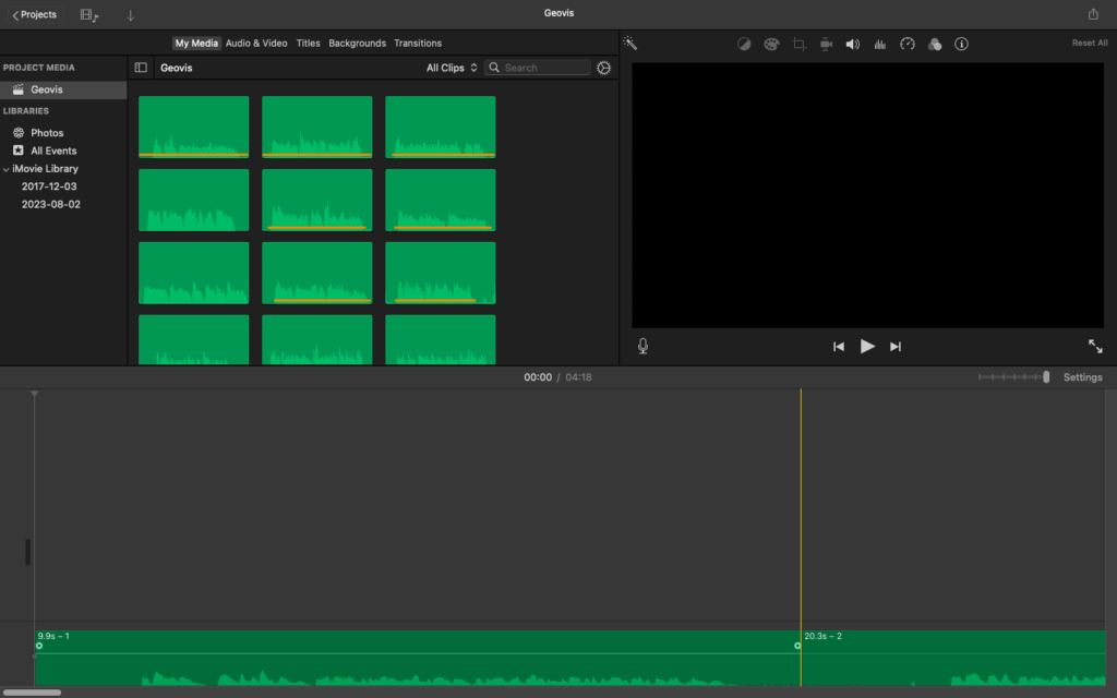
Adobe Premiere Pro is a video editing software used by many vloggers and film professionals to produce digital media online. You may add specialized glitch texts that I found on Motion Array. Don’t forget to add some music too! Since I’m uploading this video to my Youtube channel, I would have to use music that is not copyrighted content just to be safe.
Limitations
If I had all the equipment available to me to make this project as best as possible, it would be a PC with lots of RAM and a good graphics card. This way I could preview the video in detail before publishing. I’m limited by low resolution to preview the video. Moreover, with the ever changing digital media that uses VR technology, I would like to use 3D friendly plugins that lets the viewer watch the video using 3D glasses which would be spectacular. I hope you enjoy my video!
Geovisualization Project, @RyersonGeo, SA8905, Fall 2020
By Nicolas Karwowski,
Background
Sports have always been a common ground that brings together people of different ethnic and cultural backgrounds. However, regardless of the sport at hand, issues of racism have always accompanied athletic competition. With the reignition of the Black Lives Matter movement in 2020, sports teams and their players had the chance to take a stand against racism in a bigger way than ever before. In my household, we’ve followed the Toronto Raptors basketball team for many years. With this following, we have come to learn the stories of not only our own team’s players but also those of their competitors. I can reliably say that I have spent many hours learning about the hardships and the achievements of athletes from across the globe. While I do not regret spending so much time learning about the diversity of this sport, I understand that others may not have this time. This is why I have chosen to create a geovisualization that represents the complexity of an athlete’s journey to the top and the diversity of my favourite televised sport.
Data
Thankfully most widely known athletes have easily available information about their journey to the NBA. This usually includes the place they were born, the various schools they attended to hone their skills, and the professional teams they may have played for before reaching the big league. While in-depth bios exist for each team’s core roster on NBA.com, Wikipedia gives concise summaries of player’s geographic movements throughout their lives. As seen on the right, these summaries can include the player’s date of birth, place of birth, the high schools they attended and their respective locations, the college(s) they attended as well as NBA and other professional teams they might have played on. This information would be vital in the creation of points summarizing the player’s journey to athletic stardom. The main limitation of this information source is that like with other Wikipedia pages, the information could be incorrectly added, sometimes with malicious intent. Lesser known players may also have missing information. Since some players had up to 10 different locations credited in their summaries, I chose to include only ten players from the Raptor’s championship-winning 2019-2020 roster. The mention of the roster’s season is of importance as players come and go as the years go on.
Methods
For each player in the visualization, I created a new point feature class in ArcGIS Pro. I entered the points in chronological order so that when I had to connect them later with arrows, the arrows would indicate their path from place to place. Due to the number of points, their accuracy was usually only tied to the listed city’s geographical location. With all the feature classes created, I then added a few new attribute columns so that points in the final visualization could include context.
These attributes included the name of the city, the name of the country the city was located in, the type of location with regards to the player’s life (Place of Birth, School, Professional Team, NBA Team) and the player associated with that point. With this completed, I could link each of the points within feature classes using the Points To Line tool in ArcGIS. The subsequent use of the Split Line at Vertice tools was then done so that arrows could be created between points and not just at the end of the line. Using the Feature Class to Shapefile tool, I was able to export all 20 of the shapefiles, half of which were points and the other half being lines, to ArcGIS Online.
While ArcGIS Online lacks much of the symbology customization available in the desktop version, I made do with a set of simple icons. A green circle would represent the player’s place of birth, schools would be shown as blue diamonds, orange squares symbolized professional basketball and purple stars depicted NBA teams. This type of symbology allows users to understand a player’s journey to the NBA including their ups and downs.
In the final geovisualization web app, users have the ability to customize the map to whatever level they would like. If a user wishes to see where all players are born, they have the ability to turn off all layers except for the Place Of Birth layer. Clicking on any of the remaining green circles creates a pop-up that gives details on what city is there, who is born there and when they were born (as seen above). Alternatively, any and all player layers can be hidden if a user would like to focus on a single-player (as seen below).
Future work
The project as it stands only encapsulates a minuscule sample of all athletes in the NBA. Ideally, this geovisualization would enable to not only view all the Toronto Raptors players but all the players that have ever played in the NBA. When envisioning the perfect visualization, I imagine a crowdsourced app that allows anybody to add their favourite players to the app. Unfortunately, this app is non-editable and many of the steps involved required non-user-friendly applications. This visualization is also deeply limited by ArcGIS Online’s lack of symbology and UI options. These limitations include but are not limited to a search option for the layers manager as well as a grouping option for the symbology tab. Additionally, it would be very interesting to add a timeline feature in the app which allows people to see how the world of basketball has changed over the last few decades in a geographical sense.
Geovisualization Project Assignment @SA8905, Fall 2020
Introduction to Covid-19
Covid-19 is a topic at the top of many of our minds right now, and has been the subject of discussion all around the world. There are various sources of information out there, and as with most current issues, while sources of legitimate information exist, there is also a great deal of misinformation that may be disseminated. This has lead me to investigate the topic further, and to explore the patterns of the disease, in an effort to understand what has transpired in the past year and where we may be headed, as we enter into the second year of this pandemic.
Let’s begin with where it started, what the trajectory has looked like over the past year, and where it is currently as the year is coming to a close. Covid-19 is a disease caused by the new Coronavirus called SARS-CoV-2. The first report was of ‘viral pneumonia’ in Wuhan, China on December 31, 2019 and spread to all the continents except Antarctica, causing widespread infections and deaths. Investigations are ongoing, but as with other coronaviruses, it is believed to be spread by large respiratory droplets containing the virus through person-person contact. In January 2020, the total number of cases across the globe numbered 37,907 and within five months, by June 2020, the number rose to 10,182,385. We currently sit at over 6 million cases across 202 countries and territories, as of November 2020. The numbers still appear to be on a rise even with a number of countries taking various initiatives and measures in an effort to curb to spread of the disease. The data, however, shows that the death rate has been declining in the past few weeks, with a total of 1,439,784 deaths globally as of today. This is a ratio of approximately 2% of cumulative deaths to the total number of cases.
Using Tableau desktop 2019.2, I created a time lapse map of weekly reported COVID-19 cases from January 1 to November 15. Additionally, there is a graph displaying weekly reported deaths for the same date range as mentioned earlier.
I chose to acquire data from WHO (World Health Organization) because of the reputable research and their outreach globally. The global literature cited in the WHO COVID-19 database is updated daily from searches of bibliographic databases, hand searching, and the addition of other expert-referred scientific articles.
The data for this project is a .csv file that has a list of new & cumulative cases, new and cumulative deaths, sorted by country and reported date from January 1 through November 15. This list consists of data from 236 countries, territories and areas and a total of 72966 data entries for the year. For my analysis, I had a time lapse map of cases for the year, for which I used Cumulative_cases column. For the graphs representing weekly death count as well as top 10 countries by death count, I used New_deaths column.
Creating a Dashboard in Tableau Desktop
Tableau is a data visualization software which is fairly easy to use with minimum coding skills. It is also a great tool for importing large data and has the option for a variety of data to be imported as shown in the image below.
The .csv file imported opens up on the Data Source tab. There are options to open a New Worksheet and this is where we start creating all the visualizations separately and the last step would be to bring them all into a Dashboard tab.
In the side bar displayed on the left, there are Dimensions and Measures. Tableau is intelligent to generate longitude and latitude by country names. Rows and Columns are automatically filled in with coordinates when Country is added. In the Pages section, drag Date reported and this can be filtered by how you want to display the data, I chose weekly reported. In Marks section, drag and drop Category from Dimensions into Color and Cumulative Cases into Size and change the measure to sum.
By adding Date reported to Pages, it generates a Time Slider, which enables you to automatically play, choose a particular date and also set the speed setting to slow, medium or fast. The Category value generated a range for the number of cases reported weekly, which is what is shown as the changing colors on the map. Highlight country gives you an option to search for a particular country you want to view data for.
Create a new Dashboard and import the sheets that you have worked on and create a visual story. you have the option to add text, borders, background color, etc. to enhance the data.
As shown below, this is the static representation of the dashboard, which displays the weekly reported cases on the map and weekly reported deaths on the graph.
To publish to an online public portal follow the steps as shown below.
Limitations
As I was collecting data from the World Health Organization, I realized I couldn’t find comprehensive data on age groups and gender for cases or deaths. However, with the data I had, I was able to find a narrative for my story.
I had a hiccup while I was trying to publish to Tableau public from desktop. After creating an account online, I was getting an error on the desktop as shown below.
The solution to this is to go to the Data menu, scroll down to your data source, .csv files name in my case, and select Use Extract. Extracts are saved subsets of data that you can use to improve performance or to take advantage of Tableau functionality not available or supported in your original data. When you create an extract of your data, you can reduce the total amount of data by using filters and configuring other limits
Over the summer, I spotted multiple butterflies and caterpillars in my garden and became curious about what species may be present in my area and how that might change over time. Originally, I wanted to look at pollinators in general and their populations in Canada, but the data was not available for this. I reached out to the Toronto Entomologists Association (TEA) and fortunately, there was an abundant amount of butterfly population data gathered for the Ontario Butterfly Atlas. This atlas data comes from eButterfly records, iNaturalist records and BAMONA records, as well as records submitted by the public directly to TEA, therefore this data is collected by anyone who wants to submit observations. The organization had an interactive web-map (Figure 1), but this data still had more potential to be designed in a way that can engage both butterfly enthusiasts and the general public.
Technology
I chose Tableau as the platform to model this data on because it works efficiently with complex databases and large datasets. It is easy to sort and filter the data as well as perform operations (SUM, COUNT) as this was needed for some components of the dashboard. I have used Tableau in the past for simple data visualization but never for spatial data so I felt that using Tableau could be a learning experience as well as improving my skills on a software that I have used in the past.
Data & Methods:
I consulted with a contact at TEA who provided me with context on the data such as how it is gathered, missing gaps, and the annual seasonal summary on the data. Based on this information and after reviewing the dataset, I felt that there were 3 main components I could model about butterfly species in Ontario. Their location, number of yearly observations and their flight periods for adult populations. Because there was so much data, I focused on 2019 for the locational data and flight periods. There were some inconsistencies with how some of the data was recorded, mostly for number of adults observed since this was not always recorded as a numeric value, therefore any rows that did not have a numeric value were omitted from the dataset.
I chose to model the location of the species by census division because these divisions are not too small in area but are also general enough that it is easy to find the user’s location if they reside in Ontario. This resulted in a spatial join between the observation’s coordinates and the provincial census divisions’ geometry which allowed for a calculation of total sum of adults observed per census division which could also be filtered by species (Figure 2).
I modelled flight periods by month of observation of adult species because this seemed like an efficient way for the user to find when species are in their flight periods (Figure 3). Some enthusiasts may prefer this data to be modelled by month-thirds instead, but I felt that because I wanted this dashboard to be for both butterfly enthusiasts and the general public, I thought modelling by month may be easier for the user to interpret. I decided to also show this by census division because the circle size helps indicate where observations are most popular and how that compares to other census divisions. The user also has a choice to sort by census division and only visualize the flight period for that particular census division.
I modelled yearly observations starting from 2010 because submitted observations began to increase during this time due to more accessibility to online services for submissions, although data exists from the 1800s (Figure 4). This data also could only be filtered by species and not census division because this dataset with all of the observations is too big for the spatial join and caused issues with data extraction that Tableau requires for workbooks to post online.
Limitations and Future Work:
One of the biggest limitations to this dataset is the lack of observations in the northern regions compared to the southern. Because there is a lower population and less accessibility to a lot of areas, there are few submitted observations here, therefore the dataset does not capture the whole picture of Ontario.
Another limitation is that because this is citizen science-based data, there is some inconsistency with some data entry, as an example, the Adult populations were not always recorded numerically but sometimes with text or unclear values such as “a few, many, >100” which resulted in these observations not being modelled because they could not be properly quantified.
Another limitation is that the yearly observations cannot be sorted by census division. Because this contains such a large dataset, to conduct the spatial join with the census division polygons caused issues with data extraction and publishing the workbook. Therefore, this component can only be sorted by species.
The last biggest limitation to the dashboard is the way flight periods are modelled. Butterfly enthusiasts may prefer to look at flight periods within a smaller scale than months and prefer month-thirds. A future addition to this dashboard could include a toggle that allows you to switch between looking at flight period by month or month-thirds instead.
Web Experience Direct link: https://experience.arcgis.com/experience/b7a0987afdb1486fb97532788261cfd6/
Project background
The idea for this project originated from a curiosity about the numerous environmental catastrophes that the populace is often unaware of. Especially wildfires. In the last few years, every summer’s news cycle is dominated with terrible reportages about wild fires rampaging in California, British Columbia or Alberta, and rightly so, but it is often only the largest that get mentioned on TV.
Myself being from the province of Quebec, I became curious about the wildfires that happen in my home province because I haven’t heard of them quite as often as the ones in the US or the Canadian West. Fortunately, a dataset compiling data on the wildfires in the province was available on the Federal Government open data website. However, since 1976, which I assume is the year the government started compiling data on the phenomena, 60 799 wildfires happened. Since this project focuses specifically on the online aspect of things, this amount of polygons would either be impossible to draw completely or it would take too much time to draw each of the 60 799 polygons. I juggled with multiples possible solutions to remediate the issue, such as using a smaller temporal scale, but it all ultimately depended on the platform I would choose to portray the data on. Speaking of which, here’s a small description of ArcGIS Web Experience Designer.
Technology
Finding a platform to portray the data depended on my familiarity with it. Unfortunately, online GIS wasn’t my forte and I only knew of ArcGIS Online and its Story Maps. However, I felt that Story Maps were not novel enough. That’s when I happened upon the Dashboard and the Web Experience creators available on ArcGIS Online. After fiddling with both, I decided to settle on the Web Experience to portray the data.
The ArcGIS Online Web Experience is, according to their own website, a tool that allows the “creation of unique web experiences using flexible layouts, content, and widgets that interact with 2D and 3D data”. It creates a mobile-friendly output built from scratch without coding. It creates interactive maps that are formatted to be viewable and interactable on desktop, tablet and phones. It has 26 widgets available to put on the map, going from a legend to a 3D data viewer tool. For this project, I used a few simple widgets that would enhance the experience for users, which are going to be described further down.
Data and Methods
The data and methodology for this project are pretty straightforward and most of the work went into the web experience designer (to assure the optimal experience on desktop and mobile alike). The data for this project came from a vast dataset on forest fires available on the federal government’s open data website. On their page (link provided above), it is mentioned that the data was made available by multiple municipalities and government (see figure 2). However, they do also mention that the creator of the dataset is the “Secteur des Forêts-Direction des inventaires forestiers” and “Direction de la protection des forêts”, which mean “The Forest Sector-Forestry inventory direction” and “Direction of the protection of forests” respectively.
Anyway, the dataset contains data on every forest fires that occurred in the province of Quebec between 1976 and 2019. That includes geometric data on each of the polygons, the year the fire started, the way it started, the year it was “extinguished” and the superficies of the fire in hectare. Sadly, some of the variables are abbreviated and their meaning wasn’t mentioned on the website and couldn’t be used in this project, but I didn’t need them for what I intended to accomplish.
At first, I wanted to map all polygons, all 60 799, but I decided otherwise due to the sheer size of the dataset. Then, I filtered the data by the year the fires started and extracted all the data from 2013 to 2019. I hoped to display all the fires of the last few years, but even that was too big. There were a bit less than 10 000 polygons and ArcGIS Online was already giving a warning about it not being able to draw the entire thing. So, I was looking for a solution to remediate the problem of having too many polygons to draw and I figured that showing the 100 largest fires since 1976 would be indeed a very interesting, and informative, way to show what I wanted.
To that end, I filtered by the area burnt by the fire, which is in hectare, and extracted the top 100 fires. The data extraction part was done offline, on ArcGIS Pro, because it was simply faster and easier to manipulate the dataset. I then uploaded the 100 largest fires to the ArcGIS Online Platform to make a map because the Web Experience Designer couldn’t create its own map, I had to make one beforehand and then upload it to the Web Experience Designer.
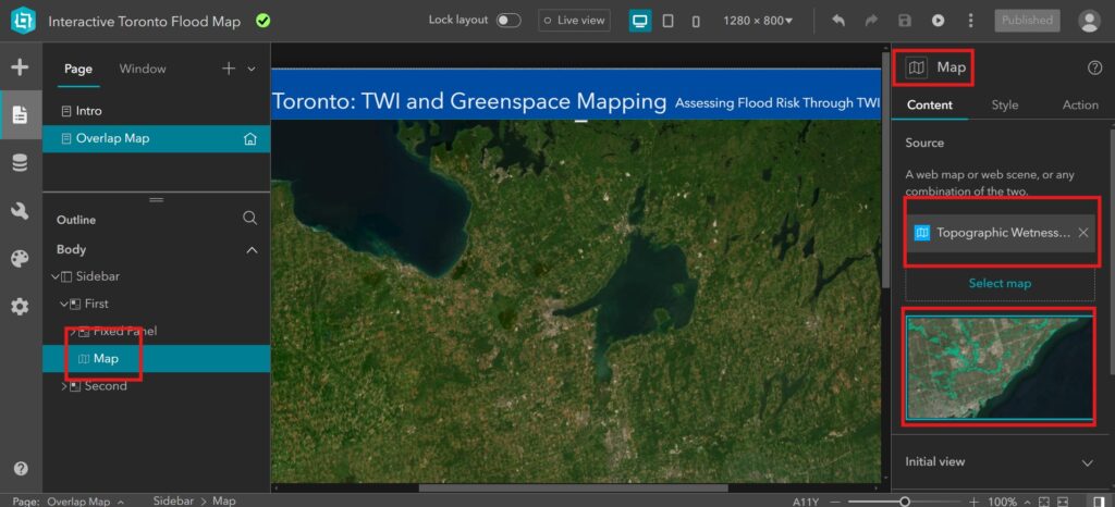
Once the map was done, I could then start working toward the creation of the web experience. Figure 3 shows the user interface of the Web Experience Designer.
The Web Experience Designer is fairly straightforward to use and is designed to be usable by people without experience in coding. All of its widgets and tools are available on the left side of the screen and usable with a simple drag and drop. Every widgets/tools are then adjustable in their settings that appears to the right side of the screen. For this project, I used the following widgets/tools: Image (which is, in fact, the legend), table, share and the button widget. Here’s a small description of each and how I used them;
Image/Legend: Sadly, legends on ArcGIS Online are very hard to modify without modifying the entire dataset and its variables and the Web Experience Designer could only use the legends from ArcGIS Online. In my case, the original legend only said “SUPERFICIE” as the field for the superficies of the fires. That wasn’t exactly what I wanted and the workaround that I used was to simply create the legend I wanted in ArcGIS Pro and then screenshot it and upload it as an image to the web experience. The result (Figure 4) shows the end result.
Table: The table widget is simple. It allows the users to see and interact with the data table of the dataset. It allows them to see almost everything there is to see in the data. For simplicity’s sake, I hid some of the more technical columns, especially those populated with the geometry data. The table only shows the fire ID, the size and the year it started. The goal was to make the experience most straightforward. The table also allows selecting specific fires without selecting them on the map (even though you also can select directly from the map).
Share: The share widget is a simple share button that any good online experience should have nowadays. I allow the users to share the link to the web experience on a multitude of social media.
Button: This widget was put on the web experience to allows the users to directly go to the source of the dataset. The link to the open data portal was already available in the web experience’s description, but this button makes it easier to use on mobile devices since you only need to click it and the link to the dataset’s source is made available.
So after making sure every widget works, the next step was to make sure that the web experience is good for each device (computers, tablets and phones). That means changing the formatting of the web experience to fit the resolution and screen sizes of each device.
Finally, the last step of the creation process was to make sure that the map was correctly interactable. That means that I tested my own web experience and verified that the polygons were selectable and that the information for the polygon appeared on screen. I made sure the data table was correct (though it seems to bug a bit as it in beta stage still) and that the polygons were drawn correctly.
Then there it was. The Web Experience was made. Only needed to write descriptions and other small paragraphs on the info page of the web experience and then publish it. I thoroughly enjoyed using the Web Experience Designer to create an interactive map, but, as much I as liked it, there were many limitations that I had to overcome.
Limitations
The limitations of this project were many, but minor. The very first one I encountered was the lack of a clear description of the variables and the abbreviations used in the data. Maybe I haven’t seen it on their page or missed it in the metadata, but I couldn’t find an explanation for some of the abbreviations they use in the data to describe the origin point (human-caused or naturally caused forest fires) and in some other variables. Knowing those could’ve led me to display the data in a much different way.
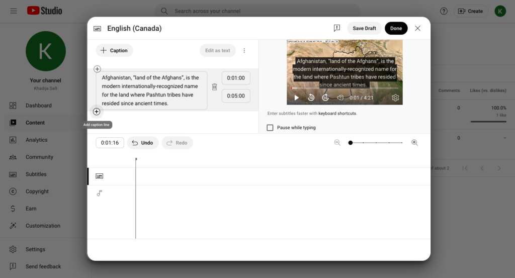
Another limit I encountered were the online capabilities of ArcGIS Online, such as the inability to draw large amounts of data, and the lack of modification to legend’s title. I could easily find other solutions by doing it offline in ArcGIS Pro, but not everyone has that ability, so I’d count that as a limitation encountered in this project.
The Web Experience Designer, while quite advanced and easy to use, was a bit of a chore to understand its intricacies and has a steep learning curve for the more in-depth features of the platform. By that, I mean that this project only uses a fraction of the options available in the Web Experience Designer. There are more widgets available, but every object part of the experience can be given actions to perform set by specific triggers. For example, If the user clicks on a polygon for a fire, it is possible to set the data table of this specific polygon to appear (in a multitude of ways) on the map. There were also many other actions and triggers to use, but the platform doesn’t make it easy for the new users to utilize the full potential of the designer.
Future Work
In a perfect world where unlimited resources were available for this project, I would make it so the web experience would display the 100 largest forest fires of the province of Quebec for every year since the start (1976).
In other words, I would set-up a year button for each of the years in the dataset. Then, the users would simply click on one (i.e. 2012) and the web experience would display the 100 largest forest fires of that chosen year. That way, the users could see a much larger dataset that would be much more informative. The top 100 forest fires show also focuses on the southern half of the province since most of the population (about 95%) lives there. So, with unlimited resources, the dataset would also include the forest fires that occurred in the northern half of the province.
In a perfect world, the dataset could include the entirety of Canada so that a top 100 forest fires could be done for each province and for every year since 1976. That would be a massive dataset however.
Utility of the project
The goal of this project was to inform the population on the locations and sizes of the wildfires in the province of Quebec. Specifically, it aims to inform fellow Quebecers of the largest forest fires that occurred in their own province. This dataset can be updated every year, if needed, to display a more up-to-date version of the wildfires. Its interactive aspects allow the users to see the information of every fire that occurred (ID, year, size, etc..). It can also be used for forestry companies and environmental agencies that wish to visualize the largest forest fires.
Janelle Lee Geo-visualization project, SA 8905, Fall 2020
Project Link:click here (use full screen mode for optimal viewing)
Background and Inspiration
In 2015, I lived in Nairobi, Kenya for eight months to participate in a work abroad internship program. On weekends, the other interns and I would explore the city—or, as they say in Nairobi, “go into town”. One of our usual excursions was to go to Toi Market, an open market beside Kibera, which is one of the largest slums in Africa. The market primarily sells clothing, shoes, and miscellaneous household items. I dug up my old travel blog documenting one of our weekend trips to Toi Market:
“The market is essentially a maze—any turn left or right takes you deeper into the layers of Toi and once inside, it’s difficult to find a way out unless you can retrace your steps. Although hot, sunny, and noisy on the outside, most of Toi is shaded and traffic is muffled by the metal-sheeted roofs and make-shift walls that divide each stall from the next. Piles of clothing extend as far as you can see and you begin to wonder where all of it came from. Many items still have their Value Village, Saver Thrift Store, or Salvation Army tags on them which gives a clue.”
I recall having a conversation with a local who told me that a clothing shipment came in every Wednesday—a seemingly infinite supply of second-hand clothing, much of which isn’t even climate appropriate. One of my most memorable images from the market is an endless wall of shelves filled with used Ugg boots (apologies for the blurry photo):
Used clothing doesn’t just stay in Nairobi. For about two weeks, I was working in Kisumu, a city in western Kenya about 450 km north-west of Nairobi. While walking around Kisumu one day, I saw a lady selling some shirts and jeans, of which included a bright red Tim Hortons t-shirt:
Seeing the volume and frequency of used clothing shipments into Kenya left an impression on how I view consumption and consumer waste, particularly in a time when minimalism and “sparking joy” by getting rid of things that we no longer use or wear have become lifestyle trends. To be fair, I haven’t read Marie Kondo’s book or watched her Netflix show, so perhaps the practices she advocates for are more nuanced and thoughtful about how and where people should get rid of their stuff. In any case, my goal for this geo-visualization project is to encourage us to be more aware and mindful of where our used clothing goes before we decide to donate it to “benefit others” (or before we even purchase new items in the first place).
Project Description
My geo-visualization includes two interactive maps and one graph:
The first map illustrates trade flow lines between countries—users can select an import and/or export country of interest to see where used clothing is shipped around the world. The other map is a choropleth map that shows whether a country is a net exporter or net importer of used clothing. Users can view the results for different years between 1995 and 2019.
The scatterplot compares each country’s GDP per capita and its net trade value of used clothing. A positive net trade value indicates that a country is a net exporter, while a negative trade value indicates that a country is a net importer. Users can press a play button to see how the scatterplot changes between 1995 and 2019. As a whole, the maps and scatterplot show a pattern in used clothing trade flows. Richer countries tend to export the most used clothing and poorer countries are the primary recipients of these shipments.
Technology
I used Tableau as the data visualization software for this project. My primary motivation for using Tableau was to learn how to use the software having no prior experience with it. I also knew that it was an effective tool for visualizing and interacting with data, and I wanted users to be hands-on with the data in my geo-visualization.
Data & Methods
The UN Comtrade Database provides international trade data for thousands of different commodities. One of these commodities is “Clothing; worn, and other worn articles”. Unfortunately, I was unable to find a more detailed description of this commodity, so I assumed that it referred to second-hand/used clothing or any kind. I retrieved the trade value (in USD) of used clothing exports between 1995 and 2019. The database also provides the weight (in kg) of used clothing shipments, but unfortunately most countries do not record their exports/imports in weight so most of this data was missing in the database (and therefore not useable).
After collecting the data from the UN Comtrade Database, I added the data into ArcMap to create a shape file of trade flow lines between countries using the “XY to Line” tool (see screenshot below). I then added this shape file to a new worksheet in Tableau where I was able to adjust the width of each line based on the trade value of used clothing shipments between countries. This formed the basis for my first map.
For my choropleth map, I first summarized the trade value data in Excel. More specifically, I calculated the following for each country: 1) the total value of used clothing exports, 2) the total value of used clothing imports, and 3) the net trade value (calculated by subtracting total imports from total exports). The net trade value data was added to Tableau and used as the variable for the choropleth map. A divergent colour scheme was applied to the map to differentiate between countries with a positive versus negative net trade value (i.e. net exporters and net importers, respectively). A filter was added to the map so users can view the results for different years between 1995 and 2019.
For the scatterplot, data on GDP per capita for each country were retrieved from the World Bank’s open data catalogue. The data were added to Tableau and a scatterplot was created using GDP per capita on the x-axis and net trade value of used clothing on the y-axis. Points on the scatterplot were made into proportional symbols to easily visualize differences in GDP per capita. An animation function was added to the scatterplot so that users can see how each country’s GDP and net trade value change over time. The United States, United Kingdom, Ghana, and Ukraine were labeled in the scatterplot to act as reference points in the graph. The US and UK are two of the top net exporters of used clothing in recent years while Ghana and Ukraine or two of the top net importers.
Geo-visualization Improvements Wish List
My initial idea for the trade flow map was to use a 3D model of the earth and animate the trade flow lines between countries. Users would be able to rotate the earth and the animated lines would more clearly and dynamically illustrate the direction of used clothing shipments (i.e. from exporter to importer).
The layout of the geo-visualization can be improved so that the balance between white space and text/visuals is more balanced when viewed on different devices. I had difficulty adjusting the layout in Tableau to be suitable for one device type without interfering with the layout on another device (e.g. smart phone versus a desktop). With the current layout, the geo-visualization elements appear much more spread out with a lot of white space in between.
When viewing the geo-visualization using the Tableau software on my computer, the playback speed of the scatterplot time lapse is fine; however, it is extremely slow when viewing it through the shareable link. I’d like to figure out how to resolve this so that the scatterplot animation doesn’t lag when others view it through the link.
For the countries that are labeled in the scatterplot (US, UK, Ghana, and Ukraine), I would like to add an outline their points so that they are easily identifiable. Currently, it’s difficult to tell which circle each label is referring to. I would also like to change the proportional symbols by reducing the number of classes for GDP per capita and increasing the size contrast between each class. Unfortunately, I wasn’t able to figure out how to customize the proportional symbols (e.g. choosing the number of classes).
Limitations & Future Work
One of the primary limitations of this geo-visualization is in the data. I only downloaded export trade value between countries, as opposed to both exports and imports. Export values are reported by the “reporting country” (i.e. the country that is exporting the commodity). The reporting country must also identify the “partner country” of that export (i.e. the country that is receiving the commodity). It was therefore assumed that the trade value of the imports received by the partner country is equal to the trade value of the exports reported by the reporting country. However, there are often mismatches between the trade value reported by the exporter and the importer because of differences in commodity valuation by different countries. The UN International Trade Statistics Knowledgebase explains this discrepancy here.
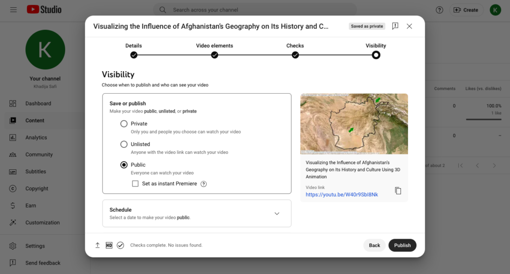
It would be interesting to supplement the geo-visualization with additional information on the total amount of second-hand clothing that each country produces (including items that get exported and those that stay within a country). This would give us a better sense of the proportion of clothing that ends up getting exported rather than staying in the domestic market.
Getting electricity to a country’s homes, different types of buildings and industries is an extremely challenging task, especially for countries that are enourmous in land area; transporting power over long distances are much more difficult. Up to now, the produced electrical energy is either very inconvenient to store or expensive, and with the increasing demand over the years in Canada, balancing betwen two in real time is crucial.
The way how electricity is generated solely depends on what kind of technologies and fuels are avaiable by that area. According to Natural Resources Canada (2020), “the most important energy source in Canada is moving water , which accounts for 59.3% of electricty supply, making it the second largest producer of hydroelectricity in the world with over 378 tearwatt hours in 2014.”
The goal of this interactive map project is to view most of the power plants in Canada and their respective sources and generating capacties (MW), which are proportional to the size of the circles shown in the project weblink above.
METHODOLOGY
In this section, I will be introducing the methdology for conducting this project. I would first describe how the data was collected, then followed by steps needed to produce the final dashboard with Tableau Public.
Data Collection
For the purpose of this study, I would need to retrieve pin-point (latitude/longitude) location of all types of power plants across Canada: from primary energy like nuclear energy and the renewables, to secondary energy that are produced from primary energy commodities like coal, natural gas and diesel. I tried looking up on various sources like Open Government Portal, but most of the open data they provide does not necessarily contain the power plants’ exact location.
Therefore, I had to manually pin-point all the data from external sources, mostly based on these two websites Global Energy Observatory (GEO) and The Wind Power. Other projects were identified by looking up on either the publicly/privately owned electricity utility company’s websites for all the provinces, for example BC Hydro, Ontario Hydro, TransAlta, etc, and their relative coordinates were retrieved using google maps. A similar interactive map “Electricity Generating Stations in British Columbia Map” has been done by researchers from University of Victoria, which provided most of the data for British Columbia and framework on what other relevant data I would like to include for my other provinces (as shown in the figure below).
In addition, all 13 provinces were accounted and a total of 612 points were collected manually.
Construction of Tableau Dashboard
Tableau Public is the software used for this project. First, load in the excel data into Tableau through Data->Open New Data Source-> Microsoft Excel. Here, make sure the latitude and longitude columns were assigned a Geographic role as shown in the snapshot below, so they could be used to map the data.
From the new worksheet screen, sections on the left corresponds to the columns of the table. Drag the non-generated latitude and longitude to columns and rows and choose the ‘symbol map’ under ‘show me’ on top right. If the ‘unknown locations’ tab pop-up from the bottom right, it means that Tableau was not able to automatically align the name of the provinces given to the column to their database, which can be simply fixed by clicking that tab and manually edit the unknown locations. After dragging in essential elements you want to present, it would look something like this as shown in the figure below. In addition, the base map can also be changed into a dark theme under Map->Background Maps.
Moving on, to create a bar/pie chart, hover the bar on the left to choose which graph would best visualize the data you are trying present, then drag essential data into columns/rows.
Last but not least, add a new ‘dashboard’ sheet and drag in all the maps/graphs into the dashboard to be the final product. Organizing the layout in the dashboard could be frustrating without the proper frame, you may also consider making elements like the filters and smaller graphs into a ‘float’ item by right clicking it, so that those ‘floating’ items could be placed on top of other elements on the dashbaord; in this case, I made the bar graph ‘floating’ so it is layed on top of the interactive map.
RESULTS & LIMITATIONS
Hydroelectricty do contribute to 56.67% of electricity generation across the country, followed by natural gas (12.39%) and nuclear energy (11.29%). However, a lot of electricity generation in Alberta are still based on coal, which takes up to 46.21% of the total capacity in that province.
Since all the data were collected manually, they may not be 100% accurate but the idea is to have a sense on where approximately it is located. For example, one single wind farm containing ten wind turbines may consist a large space across the mountain/field, the data collected was based on one wind turbine instead of plotting all ten of them.
Moreover, less developed provinces like the Northwest Territories has a very low amount of electricity generated due to its lower population (one diesel power plant per small town located using google satellite), there could have been more power plants around the area.
In conclusion, precise and consistent data is lacking for all the provinces from open data source portal, creating a potential for future similar studies carried out if more data is allowed. A time line perspective could also be added to this interactive map as well, so as users drag along the bar they can see the change in different types of powerplants that were being built in different locations.
Over the years, many homeowners have decided to turn their place of residence into short term rentals, allowing their place of residence to be rented out for short periods of time. Short term rentals have also seen an increase in popularity due to their better pricing when compared with hotels and the unique neighbourhood characteristics it provides. Although Calgary has not seen the increase of short term rentals as dramatics as that of Toronto and Vancouver, Calgary has continued to see growth in the short term rental supply. The City of Calgary defines a short term rental as a place of residence that provides temporary accommodation and lodging for up to 30 days and all short term rentals in Calgary must legally obtain a business license to run.
This interactive dashboard will aim to highlight some key components related to short term rentals in Calgary such as the locations, the license status, the composition of the housing type and licenses per month
Data
The data used in this dashboard is based off of the Short Term Rentals data set which was acquired through the City of Calgary’s Open Data Portal.
Methods
Data Cleaning – After downloading the data from the open data portal, the data needed to be cleaned for it to properly display the attributes we want. All rows containing NULL values were removed from the data set via MS Excel.
Map Production – After importing the cleaned data into Tableau, we should quickly be able to create our map that shows where the locations of the short term rentals are. To do this, drag both the auto generated into the middle of the sheet which should automatically generate a map with the location points. To differentiate LICENSED and CANCELLED points, drag the License Status column into the ‘Color’ box.
Monthly Line Graph – To produce the line graph that shows the number of licenses produced by month, drag into the COLUMN section at the top and right click on it and select MONTH. For the ROWS section, again use but right click on it after dragging and select MEASURE and COUNT. Lastly, drag License Status into the ‘Color’ box.
City Quadrant Table – To create this table, we first need to create a new column value for the city quadrant. Right click the white space under ‘Tables’ and click on ‘Create Calculated Field’ which will bring up a new window. In the new window input RIGHT([Address],2) into the blank space. This code will create a new field with the last two letters in the Address field which is the quadrant. Once this field is created, drag it into the ROW section and drag it again into the ROW but this time right clicking it and clicking on Measure and then Count. Finish off by dragging License Status to the ‘Color’ box.
Dwelling Type Pie Chart – For the pie chart, first right click on the ROW section and click ‘New Calculation’. In the box, type in avg(0) to create a new ‘Mark’. There should now be an AGG(avg(0)) section under “Marks’, make sure the dropdown is selected at ‘Pie’. Then drag the Type of Residence column into the ‘Angle’ and ‘Color’ boxes. To further compute the percentage for each dwelling type, right click on the angle tab with the Type of Residence column in it then go the ‘Quick Table calculation’ and finally ‘Percent of Total’ .
Dashboard Creation – Once the above steps are complete, a dashboard can be made with the pieces by combining all 4 sheets in the Dashboard tab.
Limitations
The main limitations in this project comes from the data. Older licensing data is removed from the data set when the data set is updated daily by city staff. This presents the problem of not being able to compare full year to date data. As seen in the data set used in the dashboard, majority of the January data has already been removed from the data set with the except of January 26, 2020. Additionally, there were also quite a few entries in the data set that had null addresses which made it impossible to pinpoint where those addresses were. Lastly, as this data set is for 2020, the COVID-19 pandemic might have disrupted the amount of short term rentals being licensed due to both the city shifting priorities as well as more people staying home resulting in less vacant homes available for short term rentals.
Geovisualization Project @RyersonGeo SA8905- Cartography and Geovisualization, Fall 2020 Author: Sridhar Lam
Introduction:
York Region, Ontario as identified in Figure 1, with over one million people from a variety of cultural backgrounds is across 1,776 square kilometres stretching from Steeles Avenue in the south to Lake Simcoe and the Holland Marsh in the north. By 2031, projections indicate 1.5 million residents, 780,000 jobs, and 510,000 households. Over time, York Region attracted a broad spectrum of business activity and over 30,000 businesses.
To create a geovisualization dashboard for the public to navigate, locate and compare established Businesses across the nine Municipalities within the Region of York.
The dashboard is intended to help Economic Development market research divisions sort and visualize businesses’ nature, year of establishment (1806 through 2018), and identify clusters (hot-spots) at various scales.
First, the Business Directory updated as of 2018, and the municipal boundaries layer files, which are made available at the Open-Data Source of York Region, are downloaded. As shown in Figure 2, the raw data is analyzed to identify the Municipal data based on the address / municipal location distribution. It is identified that the City of Markham and the City of Vaughan have a major share.
Fig.2: The number of businesses and the percentage of share within the nine Municipalities of the York Region.
The raw-data is further analyzed, as shown in Figure 3, to identify the major business categories, and the chart below presents the top categories within the dataset.
Fig.3: Major Business Categories identified within the dataset.
Further, the raw data is analyzed, as shown in figure 4, to identify the businesses by the year of establishment, and identifies that most of the businesses within the dataset were established after the 1990s.
Fig 4: Business Establishment Years identified within the dataset.
The Business addressed data is checked for consistency, and Geocodio service is used to geocode the address list for all the business location addresses. The resulting dataset is imported into ArcGIS Map, as shown in figure 5, along with the municipal boundaries layers and checked for inconsistent data before being uploaded onto ArcGIS Online as hosted layers.
Fig.5: Business Locations identified after geocoding of the addresses across the York Region.
Once hosted on ArcGIS Online, a new dashboard titled: ‘Geovisualization of the York Region 2018 Business Directory’ is created. To the dashboard, the components are tested for visual hierarchy, and careful selection is made to use the following components to display the data:
Dashboard Title
Navigation (as shown in figure 6, is placed on the left of the interface, which provides information and user-control to navigate)
Pull-Down/ Slider Lists for the user to select and sort from the data
Maps – One map to display the point data and the other to display cluster groups
Serial Chart (List from the data)- To compare the selected data by the municipality
Map Legend, and
Embedded Content – A few images and videos to orient the context of the dashboard
The user is given a choice to select the data by:
Fig.6: User interface for the dashboard offering selection in dropdown and slider bar.
Thus a user of the dashboard can select or make choices using one or a combination of the following to display the results in on the right panes (Map, data-chart and cluster density map):
Municipality: By each or all Municipalities within York Region
Business Type: By each type or multiple selections
Business Establishment Year Time-Range using the slider (the Year 1806 through 2018)
For the end-user of this dashboard, results are also provided based on business locations identified after geocoding the addresses across the York Region, comparative and quantifiable by each of the nine municipalities shown in Figure 7.
Fig.7: Data-Chart displayed once the dashboard user makes a selection.
By plotting the point locations on a map, and simultaneously showing the clusters within the selected range (Region/ by Municipality / by Business Type / Year of Establishment selections), Figure 8.
Fig.8: Point data map and cluster map indicate the exact geolocation as well as the cluster for the selection made by the user across the York Region at different scales.
Results:
Overall, the dashboard provides an effective geovisualization with a spatial context and location detail of the York Region’s 2018 businesses. The business type index with an option to select one/ multiple at a time and the timeline slider bar offers an end-user of the dashboard to drill down to the information they seek to obtain from this dashboard. The dashboard design offers a dark theme interface maintaining a visual hierarchy of the different map elements such as the map title, legend, colour scheme, colour combinations ensuring contrast and balance, font face selection and size, background and map contrast, choice of hues, saturation, emphasis etc. The maps also offer the end-user to change the background map base layers to see the data in the context of their choice. As shown in figure 9 of location data and quantifiable data at different scales, the dashboard interface offers visuals to display the 30,000+ businesses across the York Region.
Fig.9: Geovisualization Dashboard to display the York Region 2018 Business Directory across the Nine Municipalities of the York Region.
(Please note an ArcGIS Online account is required)
Limitation:
The 2018 business data across York Region contains over 38,000 data points, and the index/ legend of the business types may look cluttered while a selection is made as well. The fixed left navigation panel width is definitely a technical limitation because the pull-down display cannot be made wider. However, the legend screen could be maximized to read all the business categories clearly. There may be errors, incomplete or missing data in the compilation of business addresses. This dashboard can be updated quickly but requires a little effort, whenever there is an update of the York Region business directory’s new release in the coming years.